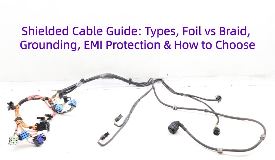
A shielded cable helps reduce the impact of electromagnetic interference (EMI) and radio frequency interference (RFI) on signal, power, and communication lines. However, adding a shield does not automatically eliminate interference. Effective cable shielding depends on shield type, coverage, interference frequency, termination, grounding, connector design, cable routing, and operating environment. Foil, braid, spiral, and combined foil-and-braid shields each serve different application requirements.
Effective shielding requires the right combination of cable construction, termination, grounding strategy, and installation. For OEM engineers and technical buyers, selecting shielded cables or shielded wire requires more than comparing materials. This blog will explains shielding types, EMI protection, grounding, troubleshooting, and practical selection criteria for EMI shielded cable assemblies.
What Does a Shielded Cable Actually Do?
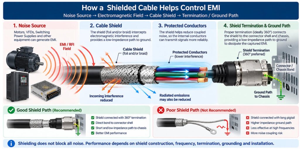
A shielded cable uses a conductive layer around a conductor, twisted pair, conductor group, or complete cable core to help reduce electromagnetic coupling between the cable and its surrounding environment.
Depending on the cable construction and system design, the shield can help:
- Reduce external EMI/RFI coupling into signal conductors
- Reduce electromagnetic emissions radiated from the cable
- Provide a controlled path for induced noise current when properly terminated
- Improve signal stability in electrically noisy environments
A simple way to visualize the function is:
Noise Source → Electromagnetic Field → Cable Shield → Termination / Ground Path
However, cable shielding does not block all electrical noise. The actual shielding effectiveness depends on several factors working together:
- Shield material
- Operating frequency
- Shield coverage
- Shield resistance
- Termination method
- Grounding strategy
- Cable routing
- Connector and chassis bonding
For example, an EMI shielded cable with good foil or braid construction can still perform poorly if the shield is left unterminated, connected through a long high-impedance pigtail, or interrupted at the connector.
In our cable assembly work, we therefore evaluate the complete shielding path rather than only asking whether the cable “has a shield.”
Shielded vs Unshielded Cable: What Is the Difference?
The main difference between a shielded cable and an unshielded cable is the presence of a dedicated conductive shield around the conductors, pairs, or cable core.
Shielded Cable vs Unshielded Cable: Key Differences
| Feature | Shielded Cable | Unshielded Cable |
|---|---|---|
| EMI Control | Better when correctly designed and terminated | Lower inherent EMI protection |
| Construction | Includes conductive shield | No dedicated conductive shield |
| Cable OD | Usually larger | Usually smaller |
| Cost | Higher | Lower |
| Termination | More complex | Simpler |
| Grounding | Shield termination must be considered | No shield grounding |
| Flexibility | Depends on shield design | Often simpler and lighter |
| Typical Environment | Industrial/noisy environments or sensitive signals | Lower-noise applications |
A shielded cable is not automatically better for every application. Shielding is valuable when there is a real EMI risk, EMC requirement, or sensitive signal path, but unnecessary shielding can increase cable diameter, weight, cost, and termination complexity.
In our experience, the correct choice between shielded vs unshielded cable should be based on the actual noise source, signal type, cable length, routing, frequency and system grounding not simply on the assumption that more shielding always means better performance.
What Are the Main Types of Cable Shielding?
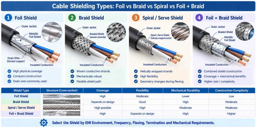
The four main types of cable shielding are foil shield, braided shield, spiral (serve) shield, and combined foil-and-braid shield. Each uses a different conductive structure to help control electromagnetic interference (EMI), with different characteristics in coverage, flexibility, electrical performance, and termination.
Choosing between these shielded cable types depends on the interference environment, cable movement, connector design, and installation requirements.
| Shield Type | Construction | Main Strength | Typical Limitation |
|---|---|---|---|
| Foil Shield | Thin metal foil laminated to film | High physical coverage, compact construction | More sensitive to flex, usually needs a drain wire |
| Braid Shield | Woven copper or tinned-copper strands | Mechanical durability and low-resistance shield path | Less than full physical coverage |
| Spiral / Serve Shield | Conductive strands wrapped helically around the cable core | Flexible and relatively easy to terminate | Coverage can change during repeated flexing |
| Foil + Braid | Combination of foil and braided shielding | Combines high coverage with stronger mechanical and electrical performance | Larger OD, higher cost, and more process complexity |
Foil Shield
A foil shield uses a thin metallic foil, commonly laminated to a polymer film, around a conductor, pair, or cable core. It provides high physical coverage while keeping the cable relatively compact.
Because foil is thin, it is usually paired with a drain wire to provide a practical termination path. In repeated-flex applications, foil construction and flex life need to be checked carefully.
Braid Shield
A braid shield is made from woven copper or tinned-copper strands.
Its main advantages are mechanical durability, flexibility, and a relatively low-resistance conductive path for shield termination. However, braid does not normally provide complete physical coverage because small openings remain between the woven strands.
Actual braid performance depends on more than coverage percentage alone. Strand size, weave pattern, material, frequency, and termination all matter.
Spiral / Serve Shield
A spiral or serve shield uses conductive strands wrapped helically around the cable core instead of woven into a braid.
This construction can provide good flexibility and is often easier to process in flexible cable assemblies. However, shield coverage can change as the cable bends or twists, so it should be evaluated against the actual movement and EMI requirements.
Foil + Braid Shield
A foil-and-braid shield combines two shielding structures in one cable.
The foil helps provide high physical coverage, while the braid adds mechanical strength, flexibility, and a more robust conductive termination path.
In our experience, this combination is often selected when both EMI performance and mechanical durability are important. The trade-off is increased cable diameter, weight, cost, and termination complexity.
Foil Shield vs Braid Shield: What Is the Difference?
The main difference between a foil shield and a braid shield is their construction. Foil uses a thin conductive layer wrapped around the cable core, while braid uses woven metal strands.
| Feature | Foil Shield | Braid Shield |
|---|---|---|
| Construction | Metal foil laminated to film | Woven metal strands |
| Physical Coverage | Very high / continuous depending on design | Depends on braid coverage |
| Cable Diameter | Usually thinner | Usually larger |
| Flex Durability | More sensitive depending on construction | Generally better for repeated movement |
| Termination | Often uses a drain wire | Can often terminate braid directly |
| Shield Resistance | Generally higher than braid | Generally lower |
| Cost | Often lower | Often higher |
| Typical Use | Data, signal, and compact cables | Industrial, flexing, and mechanically robust applications |
A foil shielded cable provides a nearly continuous conductive surface around the conductors, which helps achieve high physical coverage with relatively little added diameter.
A braided shield cable contains small openings between the woven strands, but the braid provides a mechanically stronger conductive path and is usually better suited to repeated bending or handling.
However, actual EMI performance cannot be predicted from shield material alone. It also depends on frequency, coverage, cable geometry, termination, connector transition, grounding, and installation.
In our experience, the better choice is not simply “foil or braid.” The correct shield is the one that matches the electrical requirement, flexing condition, cable diameter limit, and termination method of the complete cable assembly. Cable assembly performance depends on the complete shield system not the raw shield material alone.
When Should You Use Foil + Braid Shielding?
A foil and braid shield combines two shielding layers to provide additional protection against electromagnetic interference (EMI). The foil offers continuous physical coverage, while the copper braid provides a relatively low-resistance conductive path, mechanical durability, and more robust termination options.
When properly designed and terminated, a double shielded cable can improve shielding performance across a wider range of interference conditions. However, its effectiveness still depends on grounding, connector bonding, and cable installation.
When Is Double Shielding Necessary?
A dual shield cable is worth considering in applications such as:
- Industrial automation: Equipment operating near variable frequency drives (VFDs), motors, and switching power supplies.
- Sensitive signal transmission: Measurement instruments, industrial communication systems, and low-level signal circuits.
- High-EMI environments: Applications where EMC requirements or testing indicate that single-layer shielding is insufficient.
- Robust connector termination: Assemblies requiring circumferential shield connections through metal backshells or EMC clamps.
However, double shielding does not automatically make a cable suitable for continuous bending or torsion. Dynamic applications require an appropriately rated cable construction.
What Are the Trade-Offs?
| Factor | Foil + Braid Shielding |
|---|---|
| Cable Diameter | Usually larger |
| Cost and Weight | Higher due to additional shielding materials |
| Flexibility | May reduce flexibility or increase the minimum bend radius |
| Manufacturing | Requires more complex stripping and shield preparation |
| Termination | Requires careful handling and termination of both shielding layers |
At Yihetai, our 23 years of wire harness manufacturing experience have shown the importance of proper shield preparation and connector termination. Damaged foil, loose braid strands, or excessive shield removal can compromise cable assembly quality.
Is Double Shielding Always Better?
Not necessarily. A properly designed single-shield cable may provide sufficient EMI protection without the additional cost, diameter, and manufacturing complexity of a combination shield cable.
Double shielding is not automatically necessary; it should be justified by the EMI environment and system requirements.
For OEM applications, we recommend selecting the shielding construction based on actual EMC requirements, mechanical conditions, connector compatibility, and total manufacturing cost.
What Is Spiral or Serve Shielding?
What Is Spiral or Serve Shielding?
A spiral shield, also called a serve shield, uses conductive strands wrapped helically around the cable core.
Compared with a woven braid, this construction is simpler and can provide good flexibility, which makes a spiral shield cable useful in applications where the cable needs to bend or move regularly.
Typical advantages include:
- Good flexibility
- Relatively simple construction
- Convenient shield termination
- Lower mechanical stiffness than some braided designs
However, the shield strands are not interwoven. As the cable bends, twists, or stretches, the spacing between strands can change, which may affect physical coverage and shielding consistency.
For this reason, spiral shielding is not automatically equivalent to braid or foil shielding in EMI performance.
When comparing spiral shield vs braid, the correct choice depends on required flexibility, motion profile, shielding performance, termination method, and operating environment.
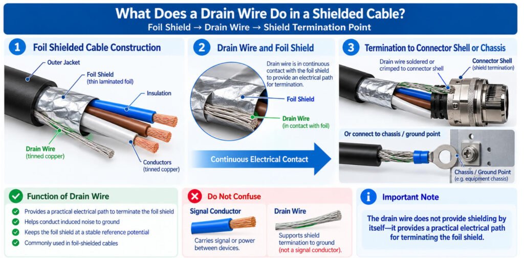
What Is a Drain Wire in a Shielded Cable?
A drain wire is a conductive wire placed in continuous electrical contact with a foil shield to provide a practical path for terminating the shield to a connector shell, chassis, or designated grounding point.
In a shielded cable, the drain wire helps establish an electrical connection between the foil shielding layer and the intended shield termination.
Foil Shield → Drain Wire → Connector Shell / Ground Point
Why Do Foil-Shielded Cables Use a Drain Wire?
Foil shields are thin and can be difficult to terminate directly. A shield drain wire, typically made from copper or tinned copper, provides an accessible conductor for making a consistent shield connection during cable assembly.
Its main functions include:
- Simplifying termination: Provides a convenient connection point without directly attaching hardware to the thin foil.
- Maintaining electrical contact: Helps connect the foil shield to the intended termination interface.
- Supporting assembly consistency: Makes shield termination easier to implement in production.
Is a Drain Wire the Same as a Signal Wire?
No. A drain wire is not a signal conductor. Its purpose is to support the shielding connection, not to carry the cable’s intended power or communication signals.
A drain wire is also not automatically a protective earth conductor. Its connection must follow the equipment’s grounding and bonding design.
Manufacturer Perspective: A shielded cable drain wire provides a practical termination method, but it does not guarantee effective EMI protection by itself. For high-frequency interference, a long drain-wire connection may introduce unwanted impedance compared with a suitable 360-degree shield termination. OEM cable assemblies should specify the drain-wire connection and shield termination method according to system requirements.
Individual Shield vs Overall Shield: What Is the Difference?
The difference between an individual shield and an overall shield is where the shielding layer is applied and what type of interference it is intended to control.
| Shield Structure | What It Protects | Typical Use |
|---|---|---|
| Individual Shield | One conductor pair, circuit, or channel | Sensitive analog, sensor, or data channels |
| Overall Shield | Entire cable core | General protection from external EMI |
| Individual + Overall | Each circuit plus the complete cable | High-noise, multi-signal, or high-reliability systems |
Individual Shielding
An individual shielded cable places a separate shield around one pair, circuit, or signal group.
This can help:
- Reduce coupling between adjacent circuits
- Protect sensitive analog or data channels
- Isolate low-level signals from noisier circuits
- Improve channel-to-channel EMC performance
Individually shielded pairs are especially useful when several different signals share the same cable.
Overall Shielding
An overall cable shield surrounds the complete cable core.
Its main purpose is to reduce electromagnetic coupling between the whole cable and the external environment.
Compared with multiple individual shields, an overall shield is generally simpler to terminate and can provide an effective common EMI barrier for the complete cable assembly.
Individual + Overall Shielding
Some demanding cables use both structures:
Individual Circuit Shield → Overall Cable Shield
This provides additional control of both internal circuit-to-circuit coupling and external EMI.
However, the trade-offs include:
- Larger cable diameter
- Additional weight
- Higher material cost
- More complex termination
- More difficult connector packaging
In our cable assembly work, we use individual shielding when specific channels need isolation and an overall shield when the primary concern is external EMI. Using both can provide stronger system-level control, but it should be justified by the signal architecture and EMC requirements.
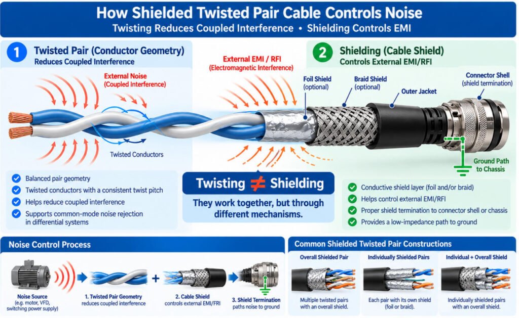
What Is Shielded Twisted Pair Cable?
A shielded twisted pair cable (STP cable) combines twisted conductors with a conductive shield to help reduce electromagnetic interference (EMI) and maintain reliable signal transmission.
The key principle is that twisting and shielding are two different noise-control mechanisms.
Twisted pairs: Two insulated conductors are twisted together to create a balanced geometry, helping reduce electromagnetic coupling and improve noise rejection in properly designed differential circuits.
Shielding: A conductive foil or braid surrounds the pairs to help control external EMI and reduce unwanted electromagnetic coupling.
Together, these features provide complementary interference protection, particularly in electrically noisy environments.
Common Shielded Twisted Pair Constructions
A shielded pair cable may use different shielding arrangements:
- Overall shielded twisted pair: One foil or braided shield surrounds all twisted pairs, helping protect the complete cable core from external interference.
- Individually shielded pairs: Each twisted pair has its own shield to help reduce crosstalk between adjacent signal circuits.
- Foil + braid combinations: Multiple shielding layers provide additional EMI control when required by the application.
When Should You Use Shielded Twisted Pair Cable?
Shielded twisted pair cables are commonly used in industrial communication, instrumentation, automation equipment, and sensitive signal transmission near motors or switching power supplies.
However, shielding is not always necessary. Properly designed unshielded twisted pairs may provide sufficient noise immunity in less demanding environments.
At Yihetai, we evaluate pair twisting, shielding structure, cable routing, and connector termination together when designing custom cable assemblies.
Twisting helps control noise through conductor geometry, while shielding provides an additional conductive structure for EMI control. Both must be considered as part of the complete system design.
Does 100% Shield Coverage Mean 100% EMI Protection?
No. 100% physical shield coverage does not mean 100% EMI attenuation or complete immunity from interference.
A foil shield can provide nearly continuous physical coverage around a cable core, but actual cable shielding effectiveness depends on much more than coverage percentage.
Important factors include:
- Shield conductivity
- Frequency of the interference
- Shield resistance
- Termination method
- Grounding strategy
- Connector transition
- Openings or gaps in the shield path
- Cable length
- Cable routing and installation
- Type and strength of the interference source
This is why 100 percent shield coverage should not be interpreted as “100% EMI protection.”
For example, a cable may use a continuous foil shield but still perform poorly if the foil is damaged during stripping, the drain wire is not terminated correctly, or the shield path becomes discontinuous at the connector.
In our experience, the connector transition is often just as important as the shield material itself.
Should a Shielded Cable Be Grounded at One End or Both Ends?
There is no universal one-end-or-both-ends rule for every shielded cable. The correct shield termination depends on signal type, interference frequency, equipment bonding, grounding topology, and EMC requirements.
| Application / Condition | Engineering Consideration |
|---|---|
| Low-level analog signal | Single-end termination may sometimes be used to reduce circulating ground current |
| High-frequency EMI | Low-impedance both-end or circumferential bonding may be beneficial or required |
| Industrial communication | Follow the equipment and interface EMC design |
| Motor / VFD / Servo | Follow the drive and motor manufacturer’s shielding instructions |
| Unknown OEM Equipment | Confirm the system grounding architecture before deciding |
When Is Single-End Shield Grounding Used?
For some low-frequency analog, instrumentation, or measurement circuits, a single-end shield termination may be used to reduce unwanted circulating current caused by ground-potential differences.
However, this approach should not be treated as a universal rule.
When Can Both-End Grounding Be Better?
At higher frequencies, a long shield connection or pigtail can add impedance and reduce shielding performance. In these applications, low-impedance bonding at both ends or a more circumferential shield termination may provide better EMC performance.
This is especially relevant when the design must control high-frequency common-mode noise
What About Motors, VFDs, and Servo Systems?
For motor drives, VFDs, and servo systems, the shield connection should follow the equipment manufacturer’s EMC instructions. These systems can generate significant switching noise, and the cable shield is often part of the complete drive-to-motor bonding strategy.
The key principle is:
One-end grounding ≠ universal shield-grounding rule.
In our cable assembly work, we do not decide the cable shield ground only from the cable itself. We first confirm the signal type, equipment grounding, connector/chassis bonding, interference frequency, and EMC requirements, then define the shield termination on the drawing.
| Application / Condition | Engineering Consideration |
|---|---|
| Low-level analog signal | Single-end termination may sometimes be used to reduce circulating ground current |
| High-frequency EMI | Low-impedance both-end or circumferential bonding may be beneficial or required |
| Industrial communication | Follow the equipment and interface EMC design |
| Motor / VFD / Servo | Follow the drive and motor manufacturer’s shielding instructions |
| Unknown OEM Equipment | Confirm the system grounding architecture before deciding |
Why Does Shield Termination Important?
A high-quality shielded cable can still perform poorly if the shield is improperly terminated at the connector or chassis. Cable shield termination determines how effectively the shielding layer maintains electrical continuity and connects to the intended grounding or bonding interface.
Poor termination can create unshielded gaps, high-impedance connections, or unreliable shield contact, reducing EMI protection even when the cable itself has suitable shielding materials.
5 Commons failure modes for your check
1.Shield Cut Back Too Far
If the foil or braid is removed too far from the connector, the exposed conductor length becomes an unshielded transition.
Longer shield cutback → larger unshielded area → greater potential EMI coupling
For high-speed or EMC-sensitive assemblies, this transition should be controlled carefully.
2.Long Drain-Wire Pigtail
A long drain-wire pigtail may provide DC continuity, but it also adds inductance.
At higher frequencies, that added impedance can reduce the effectiveness of the shield connection.
Good continuity does not always mean good high-frequency shielding.
3.Braid Not Properly Captured
If the braid is not securely captured by a crimp ferrule, shield clamp, backshell, or other termination method, the assembly may suffer from:
- Poor shield continuity
- Increased contact resistance
- Weak mechanical retention
- Intermittent EMC performance
4.Connector Shell Not Bonded
A shielded connector is only useful if the shield path is actually continued through the connector interface.
If the cable shield stops before the connector shell or chassis, the shielding path is interrupted.
5.Loose or Inconsistent Shield Termination
A loose termination may pass an initial continuity test but become unstable under vibration, flexing, or repeated handling.
This can lead to intermittent EMI problems that are difficult to reproduce during troubleshooting.
Engineers should specify shield cutback length, braid or foil termination method, connector-shell bonding, strain relief, and inspection requirements.
A properly selected shielded connector and consistent assembly process help preserve shielding continuity. However, electrical continuity testing alone does not prove EMC performance; shielding effectiveness may require additional testing under defined conditions.
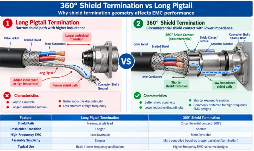
What Is 360° Shield Termination and Why Does It Important?
360-degree shield termination is a method of connecting a cable shield circumferentially to a conductive connector backshell, EMC clamp, or chassis interface.
Unlike a traditional pigtail connection, which gathers the shield into a single wire, 360° termination maintains electrical contact around the cable’s circumference.
This helps minimize inductive discontinuities and can reduce shield termination impedance, particularly at higher interference frequencies.
360° Shield Termination vs Long Pigtail
| Termination Method | Characteristics |
|---|---|
| Long Pigtail | Simple to assemble, but adds inductance and may create a longer unshielded transition |
| 360° Clamp / Backshell | Provides circumferential shield continuity and can improve high-frequency EMI performance when properly designed |
When Is 360° Shield Termination Preferred?
360 shield grounding is commonly preferred in high-frequency EMC designs where low-impedance shield continuity is important.
Typical applications include industrial automation, motor drives, servo systems, and sensitive communication equipment.
However, 360° termination is not universally required. The correct EMI shield termination method depends on signal type, interference frequency, connector design, and equipment grounding requirements.
Why Does Assembly Quality Matter?
At Yihetai, we consider shield preparation, connector compatibility, and mechanical retention essential to reliable cable assembly manufacturing.
An improperly installed EMC clamp, damaged braid, or insufficient shield contact can compromise the intended termination performance.
For OEM engineers, we recommend specifying the termination method, shield exposure length, connector backshell, and grounding requirements in the cable assembly drawing.
The key takeaway: A well-designed 360° termination can provide a lower-impedance shield connection than a long cable shield pigtail, especially in high-frequency EMI environments.
When Should You Use a Shielded Cable?
You should consider using a shielded cable when the application is exposed to significant electromagnetic interference or when the connected signal is especially sensitive to noise.
Common examples include:
- Motors
- VFDs and servo drives
- Switching power supplies
- High-current cables routed nearby
- Sensor signals
- Encoder signals
- Industrial communication
- Sensitive instrumentation
- RF-heavy environments
However, this does not mean every industrial application automatically requires shielding.
The actual decision depends on:
- Noise level and interference source
- Signal sensitivity
- Signal frequency or data rate
- Cable length and routing
- Grounding and bonding architecture
- Connector design
- Applicable equipment or EMC requirements
In our experience, why use shielded cable should always be answered by looking at the complete system rather than the industry name alone.
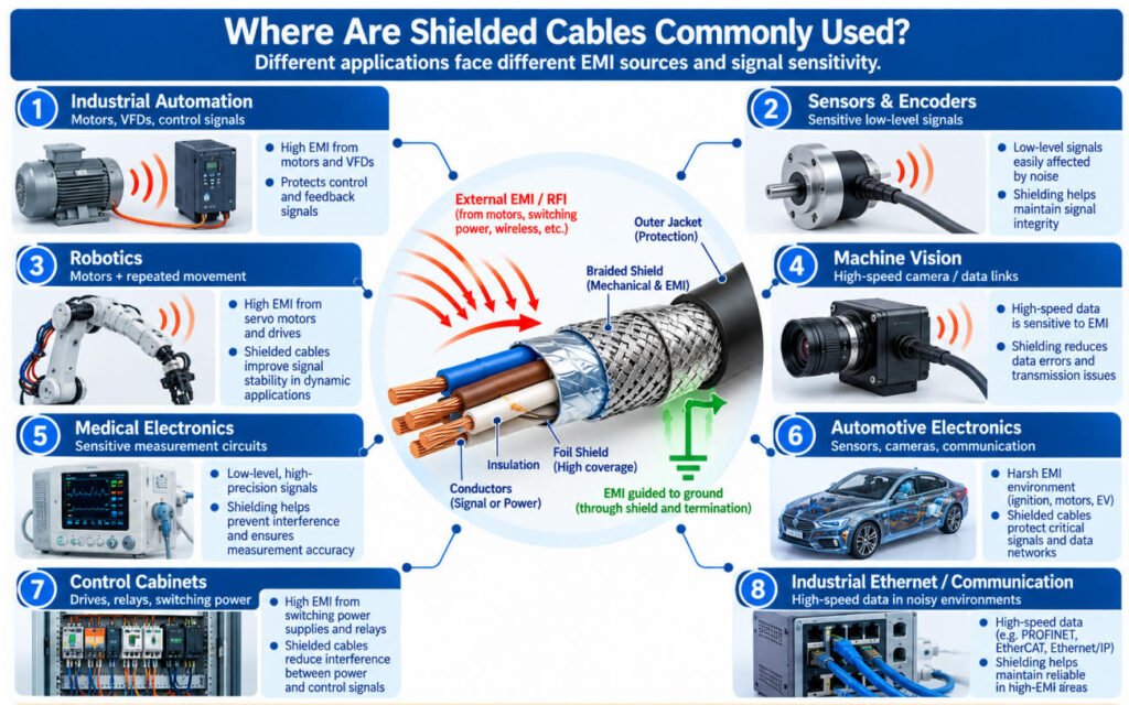
Where Are Shielded Cables Commonly Used?
Shielded cables are commonly used where sensitive signals, high-speed data, or control circuits operate near potential EMI sources. The need for shielding depends on the actual electrical environment and system design rather than the industry name alone.
Common applications include:
- Industrial Automation — Motors, relays, VFDs, and switching equipment can create EMI that affects control and communication signals.
- Sensors and Encoders — Low-level sensor and encoder signals may be sensitive to noise, especially over longer cable runs.
- Robotics — Shielding may be required alongside high-flex construction where signal cables operate close to motors and power wiring.
- Machine Vision — High-speed camera and data connections may require controlled shielding and connector termination for signal integrity.
- Medical Electronics — Sensitive measurement and communication circuits may require shielding according to the equipment design and applicable requirements.
- Automotive Electronics — Sensors, communication networks, cameras, and electronic modules can operate in electrically noisy environments.
- Test Equipment — Measurement signals often require protection from nearby electrical noise to maintain repeatable results.
- Communication Equipment — A shielded data cable may be used where EMC or signal-integrity requirements justify additional shielding.
- Control Cabinets — A shielded control cable may run near contactors, drives, power supplies, or high-current conductors.
- Audio / Video Equipment — Shielding helps reduce interference in sensitive analog and digital signal paths.
- Industrial Ethernet — Shielded constructions may be specified where network cables operate in higher-EMI industrial installations.
How Do You Choose the Right Shielded Cable?
The right shielded cable should be selected based on the complete application, not simply by choosing the cable with the most shielding.
A practical workflow is:
Signal Type → EMI Source → Frequency → Cable Length → Shield Type → Flex Requirement → Connector → Termination → Grounding → Environment
1. Identify the Signal Type
Confirm whether the cable carries analog, digital, communication, sensor, encoder, or power signals. Different signals have different sensitivity to interference.
2. Identify the EMI Source
Check for nearby motors, VFDs, servo drives, switching power supplies, RF sources, or high-current cables.
3. Consider the Interference Frequency
Shield performance changes with frequency. Do not select foil or braid based only on a simple “high-frequency vs low-frequency” rule.
4. Select the Shield Type
Choose between:
- Foil
- Braid
- Spiral / serve
- Foil + braid
The best option depends on EMI conditions, space, flexibility, and termination requirements.
5. Choose Individual or Overall Shielding
Use individual shielding when internal circuit-to-circuit coupling is a concern. Use an overall shield when the main problem is external EMI.
6. Check Cable Length and Flexing
Confirm cable length, bend radius, and whether the cable is static, occasionally moved, or continuously flexed.
7. Define the Connector Shield Path
Check whether the cable shield continues through the connector shell, backshell, clamp, or chassis connection.
8. Select the Shield Termination
Possible methods include:
- Drain-wire pigtail
- Direct braid termination
- Ferrule
- Shield clamp
- Backshell
- 360° termination
The termination method should match the frequency and EMC requirements.
9. Define the Grounding Strategy
Confirm whether the shield connects at one end, both ends, connector shell, chassis, or another defined bonding point.
10. Check the Environment
Consider temperature, oil, abrasion, vibration, moisture, installation space, and repeated movement.
Yihetai can review these specifications to support the selection and manufacture of custom shielded cable assemblies, including shield construction, connector termination, and production testing requirements.
Conclusion
Choosing the right shielded cable requires a systematic approach: Signal Type → EMI Environment → Interference Frequency → Shield Structure → Termination → Grounding → Mechanical Environment.
Effective shielded cable selection means balancing interference protection with flexibility, cable size, cost, and installation requirements. A shield alone does not guarantee EMC performance connector design, shield termination, grounding, and cable routing are equally important.
If you are developing a custom shielded cable assembly, send Yihetai your drawing, cable specifications, connector part numbers, shielding and grounding requirements, cable length, environmental requirements, or existing sample for engineering review and quotation.
Related Wire Harness Articles:
- Shielded Twisted Pair vs Coaxial Cable Which Is Best for Your Application?
- Coaxial Cable Types: A Complete Guide to Impedance, Connectors, RF Performance and Cable Assemblies
- What Are the Main Wire Harness Components? Complete Parts and Selection Guide
- Wire Strain Relief Methods: Types, Design, Testing and How to Choose the Right Solution
- How to Design a Custom Wire Harness for Harsh Environments?