

A car stereo wiring diagram shows how a vehicle’s radio connects to power, ground, speakers, and other electrical circuits, while a wire color chart only identifies conductor colors. Although aftermarket head units often follow common car stereo wire color codes, factory wiring can vary by vehicle year, model, trim level, audio package, factory amplifier, and electrical architecture. This means radio wiring colors should never be treated as universal connection instructions.
The same caution applies when looking for a GM wire harness color code. There is no single GM color chart that can safely identify every radio circuit across all Chevrolet, GMC, Buick, or Cadillac vehicles and model years. This guide explains factory versus aftermarket wiring, GM color-code differences, and how to interpret stereo wiring diagrams accurately.
What Does a Car Stereo Wiring Diagram Actually Show?
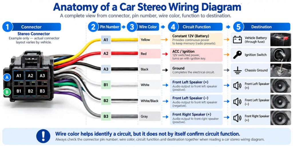
A car stereo wiring diagram shows how the radio, vehicle harness, speakers, power circuits, control circuits, and related components are electrically connected.
Depending on the vehicle and documentation source, a car radio wiring diagram may include:
- Connector ID
- Connector face or wire-side view
- Pin or cavity number
- Circuit name
- Circuit function
- Wire color
- Wire gauge where documented
- Destination component
- Splice or ground point
- Optional equipment notes
The most important point is:
Wiring Diagram ≠ Color Table
Wire color is only one identification field within the complete electrical definition.
For example, a proper radio harness diagram may show:
Connector → Pin → Wire Color → Circuit Function → Destination
That sequence matters because two wires with the same or similar color can serve different functions depending on the connector, vehicle model, system variant, or circuit location.
In our harness engineering work, we never define a connection by color alone. We confirm the connector, cavity number, circuit function, and destination first, then use wire color as an additional identification check.
How Do You Read a Car Stereo Wiring Diagram?
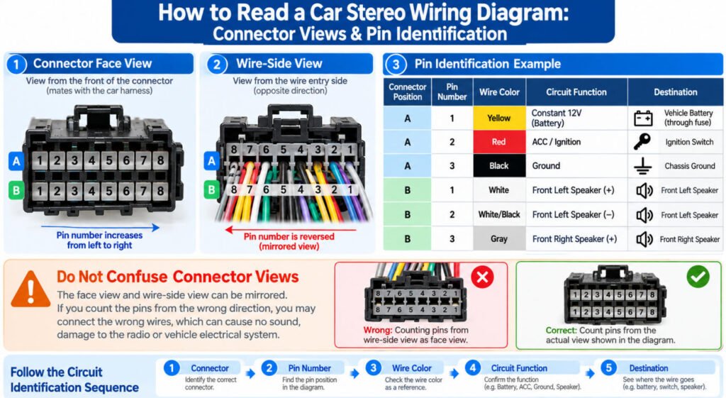
To read a car stereo wiring diagram, first identify the correct vehicle and audio system, then locate the radio connector, confirm its viewing direction, and match each pin number to its circuit function, wire color, and destination. Always verify the diagram against the vehicle’s specific wiring configuration before making connections.
The recommended workflow is:
Vehicle / Head Unit → Connector → View Direction → Pin Number → Circuit Function → Wire Color → System Variant → Verification
Step 1: Confirm the Vehicle and Audio System
Before using a radio wiring diagram, identify the vehicle’s year, make, model, trim level, and factory audio configuration. Check whether the vehicle has a factory amplifier, premium sound system, or other optional equipment.
Step 2: Identify the Correct Radio Connector
Locate the connector ID shown in the wiring documentation and match it to the corresponding connector on the radio or vehicle harness.
Step 3: Confirm the Connector Viewing Direction
This is one of the most important steps when reading a car radio pinout.
A connector face view shows the mating side, while a wire-side view shows the side where the wires enter the connector housing.
These views may appear mirrored. Counting pins from the wrong direction can result in incorrect connections, even when the wire colors seem to match.
Step 4: Locate the Pin Number and Circuit Function
Find the required pin or cavity number in the radio harness pinout, then read its circuit name and electrical function.
Depending on the system, the circuit may provide constant power, switched power, ground, speaker output, amplifier control, illumination, or vehicle communication.
Step 5: Check the Wire Color
Use the documented wire color and tracer markings to help identify the conductor. Remember that factory radio wiring colors are not universal. The same color may represent different circuits in different vehicles or audio configurations.
Step 6: Confirm the Circuit Destination
Follow the wiring diagram to determine where the circuit connects, such as a speaker, fuse, ground point, amplifier, or electronic control module.
Step 7: Review Optional Equipment Notes
Check for notes about factory amplifiers, premium audio packages, steering wheel controls, or other equipment.
Step 8: Verify the Correct System Variant
Before making any connections, confirm that the car stereo wiring diagram matches the actual vehicle and installed equipment. Compare the connector identification, pin assignments, circuit descriptions, and wire markings with the applicable service documentation.
Car Stereo Wire Colors: Factory vs Aftermarket—What Is the Difference?
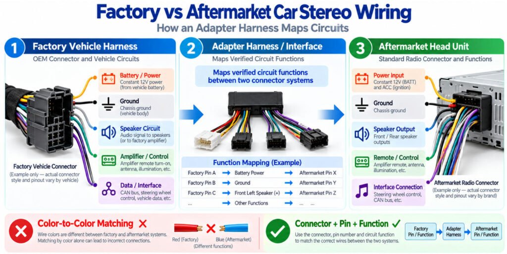
Aftermarket stereo wire colors often follow common conventions, while factory vehicle wire colors are vehicle- and system-specific and should not be assumed from an aftermarket color chart.
For example, many aftermarket head units use yellow for constant battery power, red for switched power, and black for ground. However, these car stereo wire color codes do not automatically apply to the original wiring inside a vehicle.
Factory car stereo wiring colors may vary by manufacturer, model year, trim level, audio package, and electrical architecture. Vehicles equipped with factory amplifiers or data-controlled audio systems may also require different wiring interfaces.
Factory vs Aftermarket Radio Wiring Comparison
| Item | Aftermarket Head Unit Side | Factory Vehicle Side |
|---|---|---|
| Color Convention | Often follows common aftermarket conventions | May vary by vehicle, year, and audio system |
| Function Identification | Head unit manual and harness documentation | Factory wiring diagram and service information |
| Connector | Aftermarket radio connector | OEM-specific vehicle connector |
| Amplifier / Data Integration | Depends on head unit features and interface modules | Depends on vehicle electronics and audio architecture |
| Verification | Exact head unit wiring documentation | Vehicle-specific wiring documentation and connector pinout |
Why Can’t You Match Wires by Color Alone?
A yellow wire on an aftermarket radio may indicate constant 12V power, but a yellow wire in a factory harness does not necessarily perform the same function.
The same limitation applies to speaker, illumination, and amplifier control circuits.
In our wiring harness manufacturing work at Yihetai, we rely on connector identification, terminal cavity numbers, and documented circuit assignments rather than matching conductors by appearance.
The correct rule is: Aftermarket Wire Color ≠ Factory Wire Color.
Are Aftermarket Car Stereo Wire Colors Universal?
Aftermarket stereo wiring uses widely adopted color conventions, but the installation should still be verified against the head unit and adapter-harness documentation. Although many aftermarket radios follow similar car stereo color codes, these conventions are not guaranteed across every manufacturer, connector, or audio system.
What Functions Do Aftermarket Stereo Wire Colors Identify?
Common aftermarket radio wire colors are used to distinguish several electrical functions:
- Constant Power: Supplies battery power for functions such as memory retention.
- Switched / Accessory Power: Provides an ignition- or accessory-controlled power input.
- Ground: Establishes the specified electrical return connection.
- Illumination: Supports lighting or dimming functions where applicable.
- Amplifier Remote: Provides a control signal for compatible external amplifiers.
- Speaker Pairs: Identifies the positive and negative connections for individual speaker channels.
For example, many aftermarket head units use yellow for constant power, red for accessory power, and black for ground. However, these are common conventions—not universal electrical definitions.
Why Should You Still Verify the Wiring?
An aftermarket radio wiring harness color code may differ depending on the head unit manufacturer, harness supplier, integration interface, or age of the equipment. Some installations also require vehicle-specific adapters or electronic interfaces that cannot be understood from wire colors alone.
Before connecting any wires, check the head unit manual, adapter-harness instructions, connector pinout, and intended circuit functions.
Wire Color vs Connector Pinout: Which Should You Trust?
A verified connector pinout and circuit function should take priority over wire color alone.
Wire color is useful because it helps technicians identify and trace conductors, but it is not always unique or fixed. A color may:
- Vary by vehicle or model year
- Repeat in different circuits
- Change between harness sections
- Differ by trim or audio-system configuration
A radio harness pinout, by contrast, identifies the physical terminal position inside the connector. However, the pin number is only useful when the correct connector and viewing direction have also been confirmed.
The most reliable identification method is:
Connector ID + Pin Number + Circuit Function + Wire Color
For example, if a car stereo connector pinout identifies one cavity as amplifier control, that verified circuit function should take priority over assumptions based only on the insulation color.
In our experience, many wiring mistakes happen when a technician recognizes a familiar color and stops checking the connector diagram.
Is There a Universal GM Wire Harness Color Code?
No. There is no single GM radio wire color code that can be safely applied to every Chevrolet, GMC, Cadillac, Buick, or other GM vehicle.
A GM wire harness color code can vary according to:
Year → Model → Trim → Audio Package → Factory Amplifier → Infotainment System → Connector → Circuit Assignment
For this reason, a wire-color reference found for one Chevrolet or GMC model should not automatically be applied to another vehicle. For example, seeing an orange, yellow, or other colored wire assigned to a specific function in one GM radio wiring diagram does not prove that the same color performs that function in every GM harness.
In our experience, problems occur when a color code from a different model year or audio package is treated as universal. Factory amplifiers, premium audio systems, infotainment options, and changes in vehicle electrical architecture can all affect the radio harness.
How Do You Read a GM Radio Wiring Diagram?
To read a GM radio wiring diagram, start by identifying the exact vehicle model year, model, and factory audio configuration. Then locate the correct radio connector and follow its pin assignments, circuit numbers, wire colors, and electrical functions to identify each connection.
The recommended workflow is:
Model Year → Vehicle Model → Audio System → Connector ID → Pin Number → Circuit Number → Wire Color → Circuit Function
Step 1: Confirm the Model Year and Vehicle Model
Step 2: Identify the Factory Audio Configuration
Step 3: Locate the Radio Connector ID
Step 4: Identify the Pin and Circuit Number
Step 5: Check the Wire Color and Circuit Function
Step 6: Trace the Circuit Destination
Step 7: Review Equipment-Specific Notes
Step 8: Verify Before Making Connections
How to Find the Correct GM Radio Wiring Diagram
Do not search only for “GM radio wire colors.” A broad search may return wiring information for a different vehicle or audio package.
Instead, use a more specific search format:
Model Year + GM Vehicle Model + Exact Audio Configuration + Wiring Diagram
For example:
2020 Chevrolet Silverado 1500 factory radio wiring diagram Bose amplifier
Why Can Two GM Vehicles Use Different Radio Wiring?
Two GM vehicles can use different radio wiring even if they are from the same brand or even share the same model name.
The radio harness can change because of differences in:
- Model year
- Vehicle platform
- Trim level
- Base vs premium audio
- Factory amplifier
- Infotainment architecture
- Steering-wheel controls
- OnStar or telematics
- Warning chimes
- Data-controlled functions
For example, one Chevrolet may use a relatively simple radio connection, while another version of the same model may route audio, amplifier control, chimes, or accessory functions through additional modules or data networks.
This leads to two important rules:
Same connector ≠ same wiring
and
Same model name ≠ same radio wiring across all years
A connector housing may look identical while the pin assignment or circuit function is different. Likewise, Chevy radio wire colors or other GM wire colors can change between model years and system variants.
When checking GM factory radio wiring, the safer approach is to match the exact year, model, trim, and audio configuration to the correct GM or GMC radio wiring diagram before relying on wire color or connector appearance alone.
In our harness work, we treat every system variant as a separate electrical definition until the connector, pinout, circuit function, and vehicle configuration are confirmed.
What Do Power, Ground, Speaker and Control Circuits Mean in a Stereo Diagram?
What Do Power, Ground, Speaker and Control Circuits Mean in a Stereo Diagram?
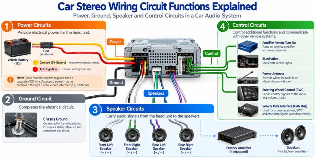
In a car stereo wiring diagram, power, ground, speaker, and control circuits describe the electrical functions of the connections between the radio and the vehicle. Each circuit serves a different purpose, and understanding these functions is more reliable than identifying wires by color alone.
For example, a car stereo power wire supplies electrical power, while car stereo speaker wires carry audio signals to the speakers. Control circuits may operate an external amplifier, antenna system, or other vehicle-integrated functions.
Common Circuit Functions in a Car Stereo Wiring Diagram
| Circuit Type | What It Does |
|---|---|
| Constant Power | Supplies continuous battery power for memory retention or other always-powered functions, where applicable. |
| Switched / Accessory Power | Provides power or an enable signal according to the vehicle’s ignition or accessory operating state, where applicable. |
| Ground | Provides the electrical return path or reference connection specified for the circuit. |
| Speaker Output | Carries audio output from the head unit or amplifier to the appropriate speaker circuit. |
| Amplifier Remote | Sends a control signal to turn a compatible external amplifier on or off. |
| Illumination / Dimmer | Supports radio lighting or brightness adjustment where the system uses a dedicated connection. |
| Antenna Control | Controls a power antenna or compatible antenna amplifier where required. |
| Data / Control | Carries communication or interface signals between the radio, vehicle modules, and related systems. |
Why Don’t My Factory Wire Colors Match the New Stereo?
Factory vehicle wiring and aftermarket stereo wiring often use different color systems, so matching wires by color alone can create incorrect connections.
The factory side is usually vehicle-specific. Wire colors, connector layouts, pin assignments, amplifier circuits, and control functions can vary by manufacturer, model year, trim level, and audio system.
The aftermarket side is different. Many radios use common aftermarket stereo wire colors for functions such as power, ground, speakers, and amplifier control.
That is why a typical installation often uses an adapter harness or interface between the vehicle and the new head unit.
Its job is not simply to make the colors match. Its real function is to:
Map the correct circuit function from the factory connector system to the aftermarket radio connector system.
For example:
Factory Connector Pin → Vehicle Circuit Function → Adapter / Interface → Aftermarket Radio Function
If your radio wiring colors don’t match, do not assume the installation is wrong or start pairing similar colors. Confirm the factory connector pinout, circuit function, adapter-harness documentation, and head-unit wiring diagram.
Why Can a Connector Fit but the Stereo Still Not Work?
A connector can physically fit while using a different pin assignment, electrical function, or system architecture.
This is why plugging a radio harness into a matching-looking connector does not automatically mean the stereo is electrically compatible.
Possible reasons include:
- Battery or accessory power is assigned to a different pin
- Speaker outputs use different terminal positions
- Amplifier turn on or control is missing
- A factory amplifier is located between the radio and speakers
- A data interface is required for certain vehicle functions
- Two connectors use similar or identical keying but different pin assignments
- Different trim levels or audio packages use different wiring
- Ground or control circuits are located in different cavities
For example, a radio harness may fit but not work because the new stereo expects switched power on one terminal while the vehicle uses that cavity for another function—or controls radio operation through a vehicle data system instead.
In our experience, connector housing shape and pin count should always be checked together with the car stereo connector pinout and circuit functions.
Physical fit ≠ electrical compatibility.
Why Does the Radio Turn On but Have No Sound?
If your car stereo turns on but has no sound, the problem may be in the speaker wiring, factory amplifier, audio signal path, or vehicle control interface not necessarily the radio’s power supply.
A radio can power on, display information, and respond to controls while producing no audio. This is especially common when replacing a factory head unit with an aftermarket stereo in a vehicle equipped with an external amplifier or integrated infotainment system.
What Causes a Car Stereo to Turn On but Produce No Sound?
If your radio powers on but has no sound, check these 7 possible causes:
- The Factory Amplifier Is Not Turning On
- The Amplifier Remote or Control Connection Is Missing
- The Audio Signal Is Routed Through a Factory Amplifier
- The Speaker Pinout Does Not Match
- A Data Interface or Integration Module Is Required
- The System Is Muted or an Audio Setting Is Incorrect
- There Is a Connector, Pin, or Wiring Fault
Why Does a Car Stereo Lose Memory When the Ignition Is Off?
If a car stereo loses memory, presets, clock settings, or other saved information after the ignition is turned off, the issue usually involves the head unit’s required constant-power circuit.
Possible causes include:
- Constant battery feed is missing or interrupted
- Switched/accessory and constant-power circuits are mapped incorrectly
- Adapter-harness wiring does not match the vehicle pinout
- Vehicle-specific power management affects radio operation
- An interface module is required but not connected or configured correctly
In many aftermarket systems, the head unit uses one circuit for continuous battery power and another for switched or accessory power. However, the exact wiring arrangement is not universal, especially on vehicles where radio power is managed through body electronics or a data interface.
In our experience, simply swapping two wires based on color can create new problems if the vehicle-side functions have not been verified first.
Loss of presets or settings usually indicates that the head unit’s required constant-power circuit is not being supplied as expected.
When a car stereo resets when the car is off, verify the wiring diagram, connector pinout, constant 12V supply, accessory circuit, and any required adapter or interface.
How Should You Verify an Unknown Car Stereo Wire?
When you need to identify an unknown car stereo wire, start with documentation and connector information before making any electrical assumptions.
The recommended verification workflow is:
Vehicle Documentation → Correct Wiring Diagram → Connector ID → Pin Number → Circuit Function → Wire Color → Approved Electrical Verification
Step 1: Find the Correct Wiring Documentation
Start with the most reliable information available:
- Factory service information: Identify the exact vehicle year, model, trim, and audio configuration.
- Head-unit manual: Confirm the aftermarket radio’s power, speaker, and control connections.
- Adapter-harness documentation: Check how the vehicle circuits are mapped to the replacement stereo.
- Connector pinout: Locate the correct connector ID, terminal cavity, and viewing direction.
- Circuit function: Confirm whether the wire carries power, ground, audio, or a control signal.
This documentation-based approach is the foundation of accurate car stereo wire identification.
Step 2: Confirm the Connector and Circuit Assignment
When learning how to identify car stereo wires, do not begin by matching insulation colors.
First, verify the connector identification and pin number against the correct radio harness pinout. Then trace the documented circuit to its intended component or destination.
Remember that two wires showing similar voltage readings may perform completely different functions.
Step 3: Perform Controlled Electrical Verification
If electrical testing is necessary, follow the vehicle manufacturer’s approved diagnostic procedures.
Depending on the circuit, appropriate verification may include checking supply voltage, ground integrity, or continuity under specified conditions.
However, how to test car stereo wires depends on the circuit type. Speaker outputs, amplifier controls, and vehicle communication lines should not be tested as though they were ordinary 12V power wires.
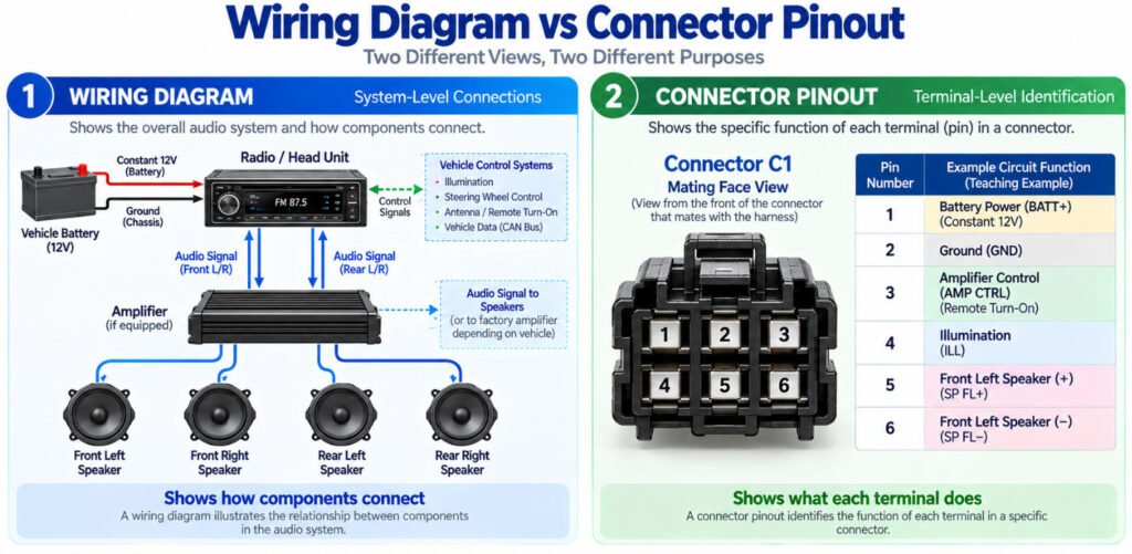
What Is the Difference Between a Wiring Diagram and a Pinout?
A wiring diagram explains how the system is connected; a pinout explains what each terminal in a specific connector does.
Both are essential for understanding a car stereo wiring diagram, but they serve different engineering purposes. A wiring diagram shows electrical relationships between components, while a car stereo pinout focuses on the terminal assignments within an individual connector.
Wiring Diagram vs Pinout: Key Differences
| Item | Wiring Diagram | Connector Pinout |
|---|---|---|
| Main Purpose | Shows circuit relationships and electrical connections | Identifies terminal positions and assigned functions |
| Scope | Complete system or individual circuit | Specific connector |
| Includes | Components, wires, splices, grounds, and connections | Pin numbers, cavity locations, and circuit assignments |
| Best For | Understanding circuit operation and troubleshooting | Connector identification, harness assembly, and terminal verification |
| Common Risk | Using a diagram for the wrong vehicle, model year, trim, or audio-system configuration | Reading the connector from the wrong viewing direction or assuming the same-looking connector uses the same pin assignments |
Conclusion
A reliable car stereo wiring diagram is more than a wire color reference. Whether you are working with factory, aftermarket, or GM radio wiring, follow this verification sequence:
Vehicle → System Variant → Connector → Pin → Circuit Function → Wire Color → Verification
Do not identify car stereo circuits by color alone. Correct connections depend on verified pin assignments, electrical functions, and vehicle-specific documentation.
If you are developing a Custom Car Stereo Wiring Harness, send Yihetai your connector part numbers, pinout, circuit functions, wire specifications, finished lengths, drawing, or existing sample for engineering review and quotation.
Related Wire Harness Articles:
- What Are the Main Wire Harness Components? Complete Parts and Selection Guide
- What Is a Wiring Harness? A Complete OEM Guide to Types, Components, Manufacturing, Testing and Supplier Selection
- Wire Gauge Guide: AWG Sizes, Diameter, Amperage & How to Choose the Right Wire
- AV Cable Guide: Types, AV InOut, Connectors, Adapters & Custom Design