
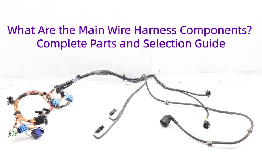
A wire harness is made from multiple electrical, mechanical, and protective components that work together to carry power, signals, and data while protecting circuits from the operating environment. The main wire harness components include wires and cables, terminals, connector housings, seals, splices, sleeving, conduit, tape, grommets, clips, strain relief, shielding, and identification labels.
In our manufacturing experience, a reliable wire harness assembly depends not only on the quality of each component, but also on whether these wiring harness components are electrically, mechanically, and environmentally compatible. A mismatch between wire, terminal, seal, or connector can create problems during crimping, assembly, testing, or field operation.
This blog we explains the functions, selection parameters, manufacturing considerations, and common failure points of major wiring harness parts, and how OEM engineers can prepare a more complete BOM for a custom cable harness.
What Is a Wire Harness?
A wire harness, also called a wiring harness or cable harness, organizes multiple wires, cables, terminals, connectors, and protective components into one installable electrical assembly. Its main functions are to distribute power, transmit signals or data, organize circuit routing, protect wiring from mechanical and environmental damage, and simplify installation during equipment assembly.
Modern wiring harnesses may range from a few simple circuits to complex multi-branch systems with shielding, seals, clips, and molded strain relief.
For a more complete explanation of how an electrical wiring harness works, its types, manufacturing process, and testing, see our What Is a Wiring Harness? Complete OEM Guide.
What Are the Main Components of a Wiring Harness?
The main wire harness components include conductors, electrical termination parts, connector components, protective materials, routing hardware, shielding, and identification parts. Each component performs a different electrical, mechanical, environmental, or manufacturing function within the complete wire harness assembly.
The following wire harness component list summarizes the most common parts of a wiring harness and the key parameters engineers should consider during selection.
| Component | Main Function | Key Selection Parameters |
|---|---|---|
| Wire / Cable | Carries power, signals, or data | Gauge, conductor material, insulation, temperature rating |
| Terminal / Contact | Creates the electrical termination | Wire range, material, plating, current rating |
| Connector Housing | Positions and protects contacts | Cavity count, keying, locking, sealing |
| Wire Seal | Seals individual wire entries | Wire insulation OD, cavity size, seal material |
| Cavity Plug | Seals unused connector cavities | Connector series, cavity size, sealing requirement |
| Splice | Joins or distributes circuits | Wire combination, current, joining method |
| Heat Shrink | Insulates and protects joints | Shrink ratio, adhesive, temperature rating |
| Conduit / Sleeving | Protects the harness bundle | Abrasion resistance, heat resistance, flexibility |
| Harness Tape | Bundles and protects wires | Temperature, abrasion resistance, noise requirements |
| Grommet | Protects wiring at panel pass-throughs | Panel hole size, cable OD, sealing requirement |
| Clip / Clamp | Secures harness routing | Bundle OD, mounting method, retention |
| Strain Relief | Reduces mechanical stress | Pull force, bend radius, flexing conditions |
| Shielding | Controls EMI/RFI | Shield coverage, grounding method, termination |
| Label / Marker | Provides identification and traceability | Material, durability, marking method |
These wiring harness parts are not selected independently. Wire gauge affects terminal selection; wire insulation diameter affects seals; terminal series determines connector housing compatibility; and bundle construction affects the choice of tape, sleeving, clips, and strain relief.
How Do Wire Harness Components Work Together?
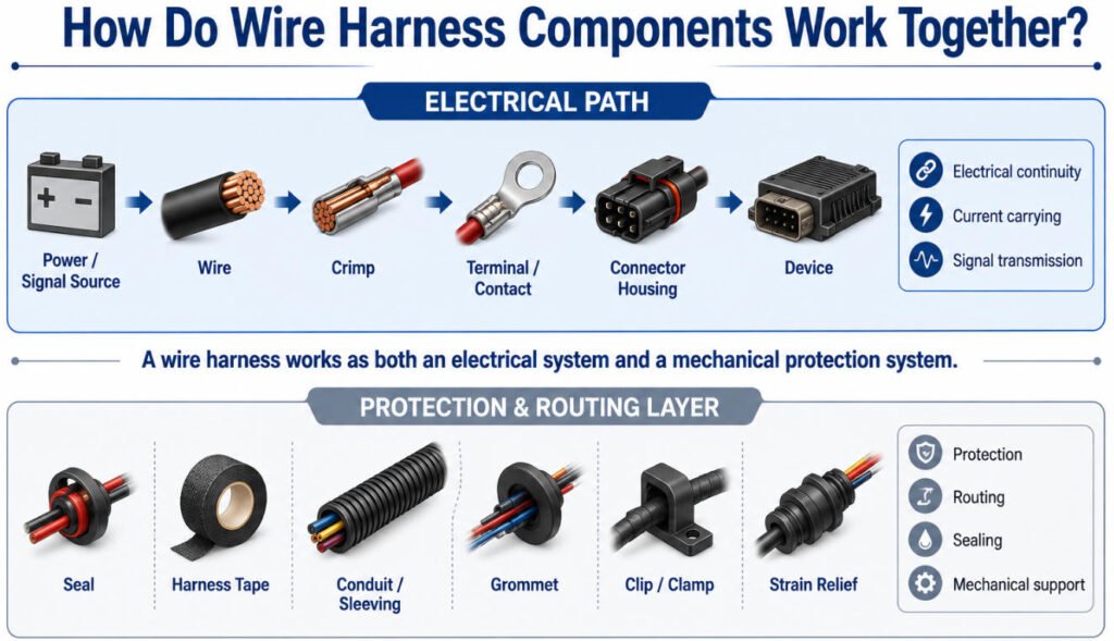
To understand how a wire harness works, it is helpful to view the harness as two interacting layers: the electrical path and the protection/routing layer.
Electrical Path
Power / Signal Source → Wire → Crimp → Terminal → Connector → Device
This path is responsible for:
- Electrical continuity
- Current carrying
- Signal transmission
Each interface must maintain low resistance and reliable contact. A problem at the crimp, terminal, or connector can affect the performance of the entire wire harness assembly.
Protection and Routing Layer
Seal + Tape + Conduit + Grommet + Clip + Strain Relief
These wiring harness components protect and position the electrical path by providing:
- Mechanical protection
- Controlled routing
- Environmental sealing
- Strain relief and support
In a complete electrical harness or cable harness assembly, both layers must work together. Good wiring harness construction means the electrical path can carry power or signals reliably while the surrounding protection and routing components help prevent abrasion, moisture ingress, excessive movement, and mechanical stress.
What Wires and Cables Are Used in a Wire Harness?
Different wire harness wire and cable types are selected according to current, signal type, temperature, flexibility, routing space, and environmental requirements. In a complete wire harness cable system, the conductor and insulation construction must also be compatible with the terminals, seals, connectors, and protection components used in the assembly.
Single-Core Wires
Single-core stranded wire is widely used for power, control, and sensor circuits. Depending on the application, conductor size may be specified in AWG or mm², and the insulation system may be selected for temperature, voltage, abrasion, chemical, or flexibility requirements.
Twisted-Pair Wires
Twisted-pair wires are commonly used for differential signals and noise-sensitive communication circuits such as CAN. Twisting the conductors helps reduce electromagnetic interference and improves signal integrity when the cable construction and system design are properly matched.
Shielded Cables
Shielded wiring harness cable is used where EMI/RFI control is important, including data, sensor, motor-control, and other noise-sensitive circuits. Shielding performance also depends on the shield construction, grounding method, termination, and connector interface.
Multicore and Special Cables
Multicore cables combine several conductors inside one outer jacket, making them useful for compact routing, signal bundles, and customized applications. Special cable harness wire may also be designed for high flexibility, elevated temperature, shielding, chemical resistance, or specific OEM requirements.
Key Wire and Cable Selection Parameters
| Parameter | Why It Matters |
|---|---|
| AWG / mm² | Determines conductor cross-section and influences resistance and current capacity |
| Conductor Material | Affects conductivity, weight, corrosion behavior, and termination |
| Strand Construction | Influences flexibility, diameter, and crimping behavior |
| Insulation Material | Determines thermal, chemical, abrasion, and environmental performance |
| Temperature Rating | Must match the operating environment |
| Voltage Rating | Must meet the electrical system requirements |
| Finished OD | Affects seals, connector cavities, routing, and bundle size |
| Flexibility | Important for vibration, movement, and installation routing |
The correct wire gauge for harness design therefore depends on more than current alone. This is especially important for automotive wire, industrial equipment, and other applications where temperature, routing, vibration, and connector compatibility can significantly influence final wire selection.
What Are Wire Harness Terminals and Contacts?
Wire harness terminals and contacts are conductive elements attached to the wire to create a reliable electrical connection. They should not be confused with the connector housing, which mainly positions, protects, and locks the contacts in place.
Different wire terminal types are selected according to conductor size, current, mating interface, environment, and assembly method.
Open-Barrel Terminals
Open-barrel crimp terminals are widely used in automotive and industrial wiring harnesses. Separate crimp sections typically secure the conductor and insulation, helping provide both electrical contact and mechanical support.
Closed-Barrel Terminals
Closed-barrel electrical terminals use a tubular crimp area around the conductor. They are used in various industrial, equipment, and power-connection applications depending on the terminal design and applicable specification.
Ring Terminals and Cable Lugs
Ring terminals and cable lugs are commonly used for grounding, battery connections, power distribution, and stud-mounted interfaces. Selection should consider conductor size, stud diameter, current requirement, plating, and environmental conditions.
Male and Female Contacts
Male and female wire harness contacts form the mating electrical interface inside a connector system. Their geometry, plating, retention features, and current rating must match the connector family and application.
Key Terminal Selection Parameters
| Parameter | Why It Matters |
|---|---|
| AWG / mm² Range | Confirms that the terminal matches the conductor size |
| Conductor Material | Affects electrical and crimp compatibility |
| Plating | Influences corrosion resistance, contact performance, and environmental suitability |
| Current Rating | Helps determine whether the contact can carry the required load |
| Crimp Geometry | Affects conductor compression and connection quality |
| Retention | Ensures the contact remains securely locked in the housing |
| Mating Interface | Must match the corresponding male/female contact and connector system |
The correct terminal wire range is especially important. A terminal that is too large or too small for the conductor can result in poor compression, damaged strands, excessive resistance, or insufficient mechanical retention.
What Is the Difference Between a Terminal and a Connector?
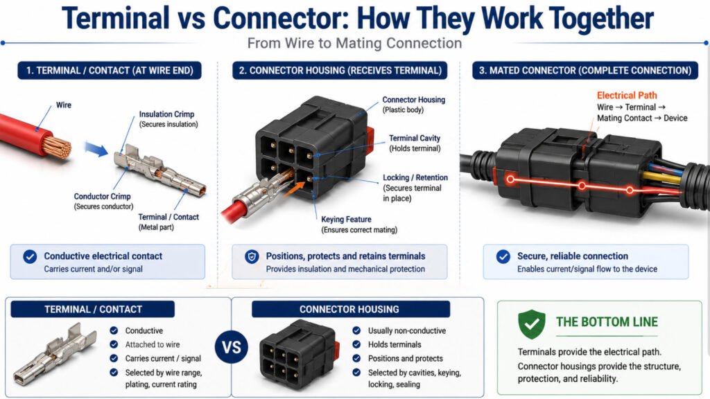
A terminal is the conductive contact attached to a wire, while a connector housing positions, protects, and locks one or more terminals into a mating interface.
In simple terms, the wire harness terminal creates the electrical connection, while the connector housing provides mechanical positioning, insulation, retention, keying, and, where required, environmental protection.
The table below summarizes the key differences between a terminal and connector:
| Feature | Terminal | Connector Housing |
|---|---|---|
| Main Function | Creates the electrical contact | Positions, protects, and retains terminals |
| Conductive | Yes | Usually no |
| Connection to Wire | Crimped, soldered, or otherwise terminated to the wire | Receives the terminated contact |
| Electrical Role | Carries current or signals | Supports the contact interface |
| Key Parameters | Wire range, plating, current rating, crimp geometry | Cavity count, keying, locking, sealing |
| Compatibility | Must match conductor size and mating contact | Must match terminal series and mating connector |
Why Terminal and Connector Compatibility Matters
Understanding terminal vs connector is important because the two components must be selected as a compatible system.
An electrical connector terminal must fit the correct housing cavity, lock securely into position, and mate correctly with the corresponding contact. At the same time, the terminal must be compatible with the wire size, conductor construction, insulation diameter, current requirement, and crimp specification.
A terminal that matches the wire but does not match the housing cannot create a reliable connector assembly. Likewise, the correct housing cannot compensate for an incorrectly selected or poorly crimped terminal.
Manufacturer Insight
In wiring harness connectors and terminals, compatibility must be verified across the complete connection:
Wire → Crimp → Terminal → Connector Housing → Mating Contact
For OEM wire harness projects, Yihetai recommends specifying the terminal and connector part numbers together whenever possible. If the exact components have not yet been finalized, wire size, insulation OD, circuit current, cavity requirements, sealing requirements, and mating-device information can be reviewed together before production.
What Types of Wire Harness Connectors Are Used?
Different wire harness connectors are used depending on what the harness connects to, the electrical load, the operating environment, and the required level of sealing or retention.
Common wire harness connector types include wire-to-wire, wire-to-board, sealed, unsealed, high-current, and signal or data connectors.
1.Wire-to-Wire Connectors
Wire-to-wire connectors join one harness directly to another harness.
They are commonly used where equipment is assembled in modules or where different harness sections need to be disconnected for installation, service, or replacement.
Typical applications include:
- Harness-to-harness connections
- Automotive sub-harnesses
- Industrial machinery
- Appliances
- Modular equipment
The selected electrical connector housing must match the correct terminal system, cavity layout, locking method, and mating connector.
2.Wire-to-Board Connectors
Wire-to-board connectors connect a harness directly to a PCB-mounted header or receptacle.
They are widely used in:
- Control modules
- Power supplies
- Sensors
- Displays
- Industrial controllers
- Consumer and medical electronics
Important parameters include pitch, cavity count, current per contact, voltage, polarization, retention, and PCB-side mating compatibility.
For compact electronics, connector pitch and available PCB space can strongly influence the final cable harness connector selection.
3.Sealed Connectors
A sealed wire connector is designed to help prevent water, dust, and contaminants from entering the contact area.
Sealed connectors are commonly used in:
- Automotive applications
- Engine compartments
- Outdoor equipment
- Construction machinery
- Agricultural equipment
- Moisture-exposed industrial systems
Depending on the connector design, sealing may be provided by individual wire seals, interface seals, gaskets, cavity plugs, or a combination of these components.
For automotive harness connectors, engineers should verify not only the connector housing but also the compatible wire seal, insulation OD, unused-cavity plug, terminal, and mating interface.
4.Unsealed Connectors
Unsealed connectors are generally used where the electrical connection is located in a protected environment and does not require direct moisture or dust sealing.
Typical applications include:
- Vehicle cabin wiring
- Internal equipment
- Control cabinets
- Appliances
- Indoor electronics
Because no environmental sealing system is required, unsealed connectors can offer simpler assembly and more compact packaging.
However, the application must still consider temperature, vibration, retention, and contamination risk.
5.High-Current Connectors
High-current connectors are designed for circuits that carry significant electrical load.
Common applications include:
- Battery systems
- Motors
- Power distribution
- Heaters
- Inverters
- Energy-storage equipment
- High-power industrial systems
For these wiring harness connectors, wire size alone does not determine the allowable current.
Engineers should also evaluate:
- Contact current rating
- Contact resistance
- Terminal size
- Temperature rise
- Connector housing temperature capability
- Number of simultaneously loaded contacts
- Cable size and flexibility
A connector contact may become the thermal limitation even when the cable itself has sufficient current-carrying capacity.
6.Signal and Data Connectors
Signal and data connectors are used where reliable transmission quality is more important than high current capacity.
Applications may include:
- Sensors
- CAN networks
- Ethernet
- Coaxial signals
- Communication systems
- Cameras
- Control and diagnostic circuits
Depending on the circuit, connector design may need to support shielding, controlled impedance, twisted-pair routing, low contact resistance, or EMI protection.
For data applications, the connector must be considered as part of the complete signal path rather than only as a mechanical interface.
What Parameters Should Be Considered When Selecting a Wire Harness Connector?
The table below summarizes the main parameters engineers should check when selecting wiring harness connectors.
| Selection Parameter | Why It Matters |
|---|---|
| Number of Cavities | Determines how many circuits can be accommodated |
| Pitch | Affects connector size, PCB layout, and contact spacing |
| Current Rating | Must support the required current per contact |
| Voltage Rating | Must meet the electrical insulation requirements |
| Sealing | Determines suitability for moisture, dust, or outdoor exposure |
| Keying | Prevents mating with the wrong connector |
| Polarization | Helps prevent incorrect orientation |
| Locking | Ensures the connection remains secure during operation |
| Mating Cycles | Important for serviceable or frequently disconnected equipment |
| Operating Temperature | Must suit the actual installation environment |
| Terminal Compatibility | The housing must match the correct terminal/contact system |
| Wire / Seal Compatibility | Important for sealed connector systems |
What Are Wire Seals, Cavity Plugs and Secondary Locks?
Seals, cavity plugs, and secondary locks are critical wire harness components in sealed connector systems. They help prevent moisture ingress, maintain terminal position, and improve connector reliability in automotive, industrial, and outdoor applications.
Single-Wire Seals
A single wire seal fits around one insulated wire where it enters the connector cavity. It seals the gap between the wire insulation and connector housing.
Common selection parameters include:
- Wire insulation OD
- Connector cavity size
- Seal material
- Temperature rating
- Oil and chemical resistance
An automotive wire seal is commonly used in engine-bay, underbody, and other moisture-exposed harness locations.
Mat / Family Seals
Mat seals, also called family seals, provide sealing for multiple connector cavities through one molded sealing element. They are commonly integrated into multi-pin sealed wire harness connector systems.
The seal must match the connector family, cavity layout, wire OD range, and operating environment.
Cavity Plugs
A cavity plug or connector cavity plug closes an unused connector cavity so water, dust, or contaminants cannot enter through an empty position.
This is particularly important when a sealed connector housing has unused circuits.
TPA / Secondary Locks
Terminal Position Assurance (TPA) components act as a secondary terminal-retention feature. After terminals are inserted into the housing, the TPA or connector secondary lock helps confirm that the contacts are fully seated and reduces the risk of terminal back-out.
A TPA should not be used to force an incorrectly inserted terminal into position.
CPA
A CPA connector feature, or Connector Position Assurance device, helps confirm that two mating connector halves are fully engaged and locked.
TPA and CPA perform different functions:
- TPA: verifies terminal retention inside the connector
- CPA: verifies connector-to-connector mating and locking
Key Selection Parameters
When selecting a wire harness seal, connector seal, or locking component, engineers should verify:
- Actual wire insulation OD
- Connector cavity size
- Connector family
- Seal and housing material
- Operating temperature
- Oil / fuel / chemical exposure
- Moisture and sealing requirements
- Terminal and connector compatibility
How Must the Wire, Terminal, Seal and Connector Match?
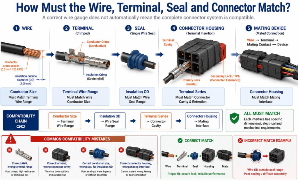
Correct wire harness component selection depends on compatibility between the wire, terminal, seal, connector housing, and mating interface. Even if each component is individually suitable, the complete connection can still fail if the dimensional or mechanical interfaces do not match.
A simple compatibility chain is:
Conductor Size → Terminal Wire Range
Insulation OD → Wire Seal Range
Terminal Series → Connector Cavity
Connector Housing → Mating Interface
Key Compatibility Relationships as follow table:
| Parameter | Why It Matters |
|---|---|
| Number of Wires | Determines splice geometry and process feasibility |
| Individual Wire Size | Each conductor must be suitable for the selected splice process |
| Combined Cross-Section | Determines total conductor volume at the splice |
| Conductor Material | Influences electrical behavior and joining compatibility |
| Electrical Resistance | The splice should not create excessive resistance in the circuit |
| Pull Strength | Indicates the mechanical integrity of the joint |
| Splice Location | Affects routing, flexing, serviceability, and environmental exposure |
| Insulation / Protection | Protects the completed splice from shorts, abrasion, moisture, or contamination |
| Bundle Diameter | The splice can increase local harness thickness and affect routing |
| Branch Layout | Determines how wires enter and leave the splice and affects package size |
The terminal wire range must match the conductor cross-section so the crimp can achieve the required electrical and mechanical performance. At the same time, the wire insulation outside diameter must fall within the specified wire seal size or connector seal size range.
The terminal itself must also belong to the correct series for the connector cavity, including the proper retention and locking features. Finally, the connector housing must match the intended mating connector, PCB header, sensor, motor, or other device interface.
For reliable wire harness connector selection, engineers should review conductor size, insulation OD, terminal geometry, seal dimensions, cavity compatibility, locking features, and the mating interface as one complete system rather than as separate parts.
What Are Splices in a Wire Harness?
A wire harness splice joins two or more conductors to create a common electrical connection or distribute one circuit into multiple branches.
A simple example is:
Power Feed → Splice → Device A + Device B + Device C
In a wiring harness splice, the joining method must provide reliable electrical continuity, mechanical strength, and suitable insulation or environmental protection.
Crimp Splices
A crimp splice joins conductors through controlled mechanical compression using a splice terminal or sleeve. Correct tooling, conductor insertion, compression, and pull strength are important to maintaining low resistance and mechanical reliability.
Ultrasonic Wire Splices
An ultrasonic wire splice uses high-frequency mechanical energy to weld conductor strands together without adding solder. Ultrasonic wire welding is widely used where multiple conductors must be joined compactly and consistently, especially in automotive and high-volume harness production.
Soldered Splices
Soldered splices may be used where the applicable drawing, product specification, or customer requirement allows them. Because solder can affect conductor flexibility and stress distribution, the splice method should always match the application and required workmanship standard.
What Parameters Should Be Considered When Designing a Harness Splice?
The design of a wiring harness splice should consider both electrical and mechanical requirements.
| Parameter | Why It Matters |
|---|---|
| Number and Size of Wires | Determines whether the splice method can accommodate the required conductor combination |
| Combined Conductor Cross-Section | Helps select the correct crimp splice, ultrasonic welding setting, or joining process |
| Electrical Resistance | Excessive splice resistance can increase voltage drop and localized heating |
| Pull Strength | Confirms that the splice has sufficient mechanical integrity |
| Splice Location and Protection | Affects routing, bundle diameter, flexibility, insulation, and environmental protection |
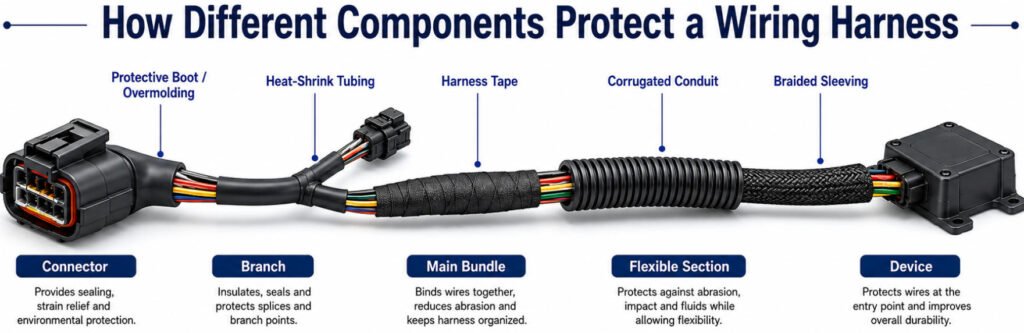
What Components Protect a Wiring Harness?
Wire harness protection components help protect wires, terminals, splices, branches, and connector exits from abrasion, heat, vibration, moisture, mechanical damage, and routing stress.
Common wiring harness protection materials include corrugated conduit, braided sleeving, harness tape, heat-shrink tubing, and protective boots or overmolding.
The correct protection method depends on the application environment, harness routing, flexibility requirements, bundle diameter, temperature, and customer specification.
Corrugated Conduit
Corrugated conduit is widely used for mechanical protection and routing. Its ribbed structure helps protect wires from abrasion and impact while allowing the harness to bend around vehicle or equipment structures.
It is commonly used in automotive, industrial, and machinery harnesses where the bundle passes through exposed or high-wear areas.
Braided Sleeving
Braided wire loom or expandable sleeving provides flexible abrasion protection around a bundle. It can expand over connectors or varying bundle diameters and is useful where flexibility and serviceability are important.
The sleeve material should be selected for the required temperature, abrasion, chemical, and flame-performance conditions.
Harness Tape
Wire harness tape is used for bundling, branch formation, abrasion protection, and local noise reduction.
Common options include:
- PVC tape
- Cloth or fleece harness tape
- PET or other high-temperature tapes
The correct tape material depends on the application specification, temperature, fluids, abrasion, and installation area.
Heat-Shrink Tubing
Heat shrink tubing is commonly used for splice insulation, transitions, sealing, identification, and local strain relief.
Adhesive-lined heat shrink can provide additional environmental sealing where required, while standard tubing may be used mainly for insulation and mechanical protection.
Protective Boots and Overmolding
Protective boots and wire harness overmolding are often used around connector exits, branch transitions, and other high-stress locations.
They can provide:
- Strain relief
- Bend control
- Mechanical protection
- Moisture protection
- Custom routing geometry
In our production line, wiring harness protection is selected based on the actual routing and environment rather than using one protection material across the entire assembly. A harness may combine conduit, wire harness sleeving, tape, heat shrink, and overmolded protection in different areas to achieve the required balance of flexibility, abrasion resistance, sealing, and manufacturability.
What Are Grommets and Strain Relief Components Used For?
Grommets and strain relief components protect wire harness transition points from abrasion, pulling, bending, and mechanical stress.
They are commonly used where a harness passes through a panel, exits a connector, changes direction, or enters an enclosure.
These areas often experience higher mechanical loading than straight sections of wire, so the correct wire harness grommet or wire harness strain relief can help improve durability and reduce damage to the cable or insulation.
Grommets
A wire harness grommet or cable grommet is commonly installed where a harness passes through a panel, enclosure, sheet-metal opening, or bulkhead.
Its main functions are to:
- Prevent abrasion against sharp edges
- Isolate the harness from the panel
- Help control bundle position
- Support sealing where required
The wiring harness grommet should match the panel opening, panel thickness, bundle OD, and environmental requirement.
Strain Relief Boots
A harness boot helps reduce mechanical stress where wires exit a connector, housing, or branch point.
It can help control:
- Pulling force
- Repeated bending
- Bend radius
- Connector exit stress
A properly designed wire harness strain relief reduces the chance of conductor fatigue or insulation damage near the termination area.
Molded Strain Relief
Molded strain relief is used when higher mechanical protection, sealing, repeatable geometry, or environmental resistance is required.
It can be overmolded directly around the cable and connector interface to provide controlled flexibility and stronger protection against pulling, moisture, vibration, and repeated handling.
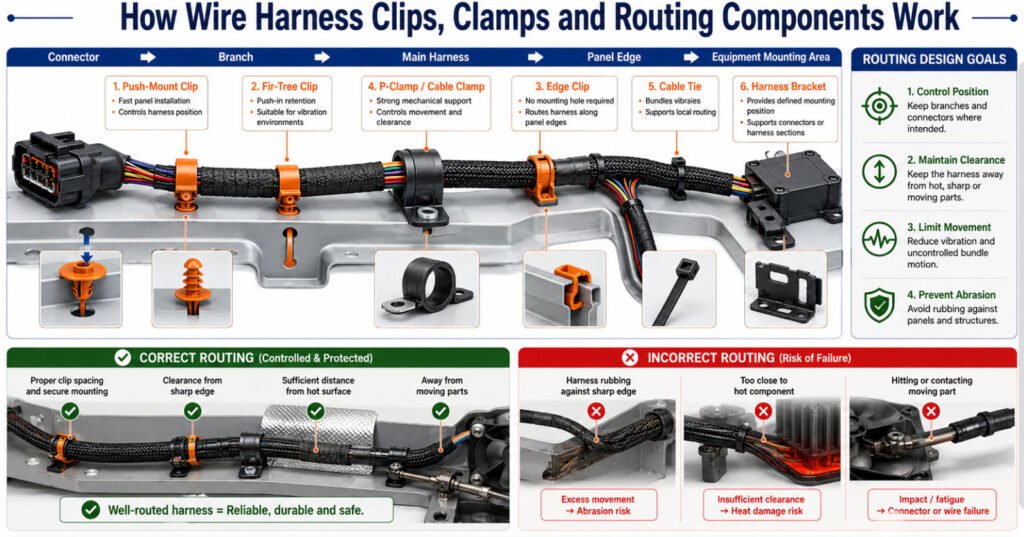
What Are Wire Harness Clips, Clamps and Routing Components?
Wire harness clips, clamps, and routing components secure the harness in the intended position and help control movement, clearance, branch location, and installation repeatability. Proper wire harness routing is important because an electrically correct harness can still be damaged if it moves excessively or contacts sharp, hot, or rotating parts.
Push-Mount Clips
Push-mount wire harness clips are designed to secure a harness to a panel or mounting hole through a push-in fixing feature. They are commonly used where fast and repeatable installation is required.
Fir-Tree Clips
Fir-tree clips use flexible retention ribs to lock into a mounting hole. These wire harness mounting clips are widely used in automotive and equipment applications where vibration resistance and quick installation are important.
Edge Clips
Edge clips attach directly to the edge of a panel without requiring a drilled mounting hole. They are useful where the harness must be routed along sheet metal, brackets, or structural edges.
P-Clamps and Cable Clamps
P-clamps and other cable clamps hold the harness securely while helping control bundle movement and maintain clearance from surrounding components. Depending on the design, they may also provide cushioning or abrasion protection.
Cable Ties
Cable ties are commonly used to bundle wires, secure branches, and support local routing. Tie material, tension, spacing, and installation method should be appropriate for the harness environment.
Brackets
Brackets provide a fixed mounting point for harnesses, connectors, clips, or clamps where additional structural support is required. They are often used in larger assemblies or areas with defined routing geometry.
Typical functions of harness clamps and routing hardware include:
- Controlling branch position
- Maintaining clearance from surrounding parts
- Preventing excessive movement
- Reducing abrasion risk
- Supporting repeatable installation
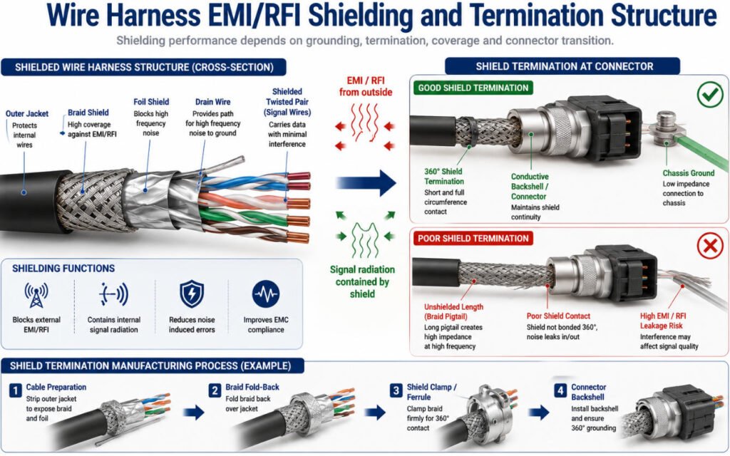
What Components Provide EMI and RFI Protection?
Wire harness shielding is used to reduce electromagnetic interference (EMI), radio-frequency interference (RFI), and unwanted signal radiation. Depending on the application, a shielded wire harness may use several shielding components together rather than relying on a single cable layer.
Common shielding components include 6 types:
- Foil shield — provides lightweight, high-coverage shielding around conductors or cable pairs.
- Braid shield — uses woven metal strands for durable, flexible shielding.
- Drain wire — provides a convenient electrical path for terminating a foil shield to ground.
- Shielded twisted pair — combines differential-pair geometry with shielding for noise-sensitive data or sensor circuits.
- Shield termination — connects the cable shield to ground, chassis, connector, or backshell.
- Conductive connector / backshell — may be used where continuous shielding through the connector interface is required.
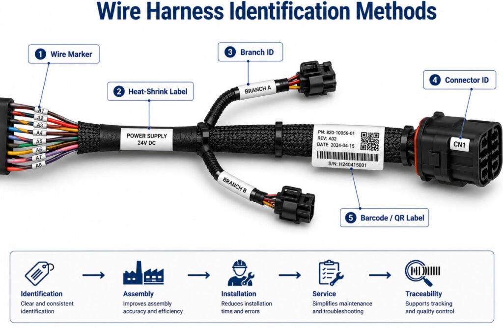
What Are Labels and Identification Components Used For?
Wire harness labels and identification components help operators, installers, and service technicians identify wires, connectors, branches, and finished assemblies throughout production and field use.
Common identification include blow 6 methods:
- Wire markers and cable markers
- Printed adhesive labels
- Heat-shrink labels
- Connector ID labels
- Branch ID labels
- Barcode or QR identification where required
Effective wiring harness labeling supports correct assembly, faster installation, maintenance, and harness traceability. It can also help link a harness to production records, inspection results, or lot information when the project requires traceable manufacturing data.
When selecting wire identification materials, engineers should consider print durability, temperature, abrasion, chemicals, adhesion, and whether the marking must remain readable for the expected service life.
How Do OEM Engineers Select Wire Harness Components?
Good wire harness component selection starts with the application requirements, not with individual parts. OEM engineers normally define electrical load, environment, routing, movement, service needs, and applicable standards first, then select the wire, terminal, connector, seal, protection, and mounting components as one complete system.
| Design Requirement | Components Most Affected | Typical Manufacturing / Engineering Parameters |
|---|---|---|
| Current | Wire, terminal, connector | AWG/mm², continuous/peak current, terminal rating, contact resistance |
| Voltage | Insulation, terminal spacing, connector | Voltage rating, creepage/clearance where applicable, insulation thickness |
| Temperature | Wire, housing, seal, sleeve | Material temperature rating, ambient °C, temperature-rise limit |
| Moisture | Connector, seal, grommet, heat shrink | Wire OD, seal range, cavity plug, sealing method |
| Vibration | Terminal lock, connector, clip, strain relief | Pull force, terminal retention, clip spacing, connector locking |
| Flexing | Wire construction, sleeve, strain relief | Strand construction, bend radius, flex direction, cycle requirement |
| EMI / EMC | Twisted pair, shielding, connector | Twist pitch, shield coverage, drain wire, shield termination length |
| Abrasion | Tape, conduit, sleeving | Sleeve wall, overlap, conduit size, protection length |
| Installation Space | Wire OD, connector, branch design | Bundle OD, branch length, connector orientation, bend radius |
| Serviceability | Connector, label, clip | Mating cycles, label position, clip position, connector access |
Manufacturing Parameters That Should Be Reviewed During Component Selection
A component may look suitable on a BOM but create production problems if its manufacturing limits are not checked. In our engineering reviews, we commonly verify:
- Wire cut length — mm with drawing tolerance
- Strip length — mm with process tolerance
- Conductor size — AWG / mm²
- Finished insulation OD — critical for seals and connector cavities
- Crimp height — mm according to terminal specification
- Crimp width — where specified
- Conductor brush length — confirms correct conductor position
- Bellmouth — checked visually or dimensionally
- Insulation support position — prevents conductor stress
- Pull force — N according to wire/terminal requirement
- Terminal insertion depth — confirms full seating
- Secondary-lock engagement — TPA / CPA condition
- Seal insertion position — prevents leakage or terminal interference
- Branch length — mm with tolerance
- Clip location — mm from drawing reference
- Connector orientation — angle / keying direction
- Minimum bend radius — based on wire or cable construction
- Bundle OD — important for conduit, sleeve, grommet, and routing space
For example, increasing a conductor from 0.5 mm² to 0.75 mm² may improve current capacity, but it can also change the finished wire OD, terminal barrel size, crimp height, seal selection, bundle diameter, and bend radius. The electrical change therefore becomes a manufacturing change as well.
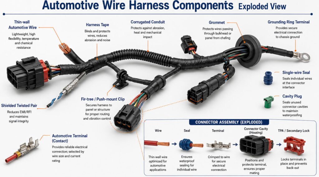
What Components Are Used in Automotive Wiring Harnesses?
Automotive wire harness components are designed to withstand vibration, temperature changes, moisture, abrasion, fluids, and limited installation space.
Common automotive wiring harness include below 11 parts:
- Thin-wall automotive wire
- Automotive terminals
- Sealed automotive harness connectors
- Automotive wire seals
- Cavity plugs
- TPA / CPA components
- Corrugated conduit
- Harness tape
- Grommets
- Clips and clamps
- Grounding terminals
- Shielded data cables
These vehicle wiring harness components must be selected as a compatible system. For example, the conductor size must match the terminal range, the wire insulation OD must match the seal, and the terminal must fit the connector cavity and locking system.
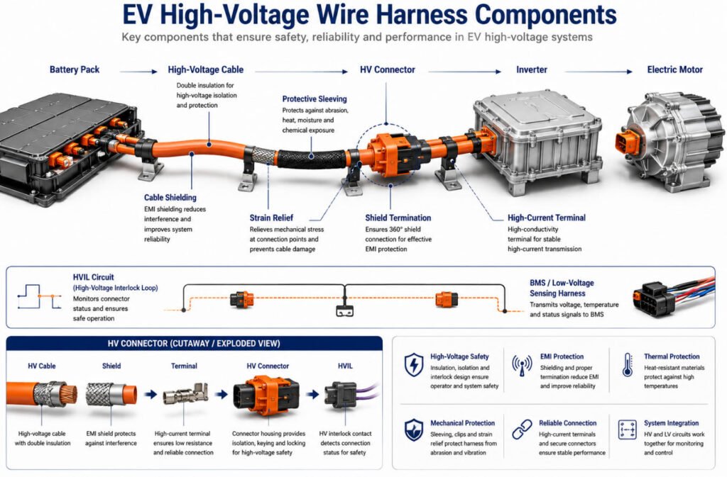
What Components Are Used in EV Wiring Harnesses?
EV wiring harness components usual include below 8 parts:
- High-voltage cable
- HV connectors
- High-current terminals
- Shielding
- HVIL circuits
- BMS wiring
- Battery connections
- High-voltage protective sleeving
For high voltage harness components, engineers typically consider voltage class, current, cable OD, bend radius, shielding, connector compatibility, sealing, and temperature requirements.
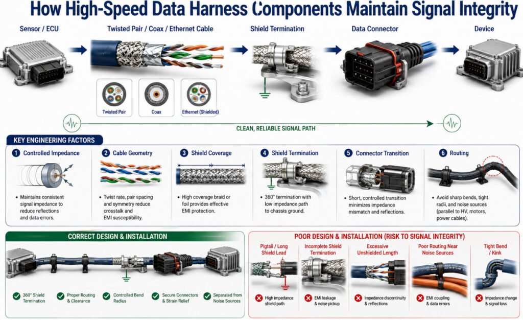
What Components Are Used for High-Speed Data and Signal Circuits?
A high speed wiring harness uses cable and connector components designed to maintain signal integrity, not just electrical continuity. Depending on the application, common components include below 7 parts:
- Twisted pair
- Shielded twisted pair
- Coaxial cable assembly
- Automotive data cable
- Automotive Ethernet cable
- Data connectors
- Shield termination components
These components are commonly used in sensors, cameras, CAN, Ethernet, RF, and other high-speed communication circuits.
For an automotive Ethernet harness or other signal wire harness, performance depends on more than conductor continuity. Engineers must also consider:
- Controlled impedance
- Shielding effectiveness
- Connector geometry
- Shield termination
- Pair twist and cable construction
- Routing near high-current or noise-generating circuits
Conclusion
A reliable harness is built from many wire harness components, but component quality alone is not enough. The wire, terminal, connector, and seal must be electrically and mechanically compatible, while protection and routing wiring harness parts must support the actual environment and installation.
For an OEM wire harness, correct component matching helps reduce crimp, sealing, abrasion, routing, and long-term reliability problems.
If you are developing a custom wire harness, send Yihetai your drawing, BOM, connector and terminal part numbers, wire specifications, or sample for an engineering review and quotation from an experienced wire harness manufacturer.
Related Wire Harness Articles:
- What Is a Wiring Harness? A Complete OEM Guide to Types, Components, Manufacturing, Testing and Supplier Selection
- Wire Gauge Guide: AWG Sizes, Diameter, Amperage & How to Choose the Right Wire
- Wire Strain Relief Methods: Types, Design, Testing and How to Choose the Right Solution
- How to Choose the Right Heat Shrink Tubing for Your Wire Harness?
- Automotive Wire Harness Protection Materials: Corrugated Tube, Tape, Sleeves and Foam Compared