
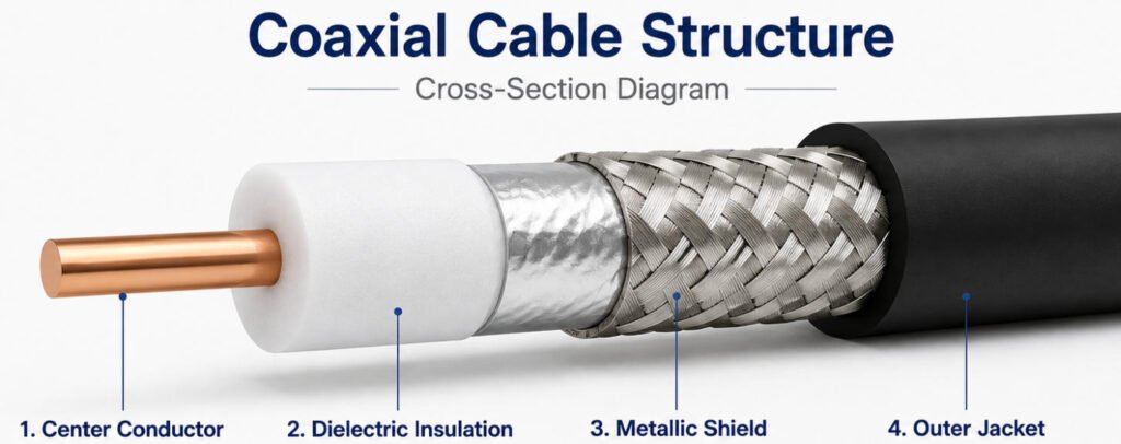
A coaxial cable is a shielded electrical cable designed to transmit high-frequency signals through a center conductor surrounded by dielectric insulation and an outer conductive shield. A typical coax cable includes four main layers: the center conductor, dielectric insulation, metallic shielding, and an outer protective jacket.
This construction helps control electromagnetic interference and maintain stable signal transmission, which is why RF coax cable is widely used in communication, antenna, video, automotive, medical, and industrial applications.
Different coaxial cable types vary in impedance, diameter, attenuation, shielding effectiveness, flexibility, and usable frequency range. This blog explains common RG cables, 50Ω vs 75Ω designs, connectors, performance factors and how to select the right coaxial cable assembly for your application.
What Is a Coaxial Cable?
A coaxial cable is a type of electrical cable designed to carry high-frequency signals while controlling impedance and reducing electromagnetic interference. The name “coaxial” comes from its structure: the center conductor and the outer conductive shield are arranged around the same geometric axis.
Unlike a basic insulated wire, a coax cable uses several coordinated layers to maintain stable RF performance.
What Are the Main Parts of a Coaxial Cable?
Center Conductor → Dielectric → Shield → Outer Jacket
- Center Conductor – Carries the RF or electrical signal.
- Dielectric – Keeps the conductor centered and helps maintain the cable’s electrical characteristics and impedance.
- Shield – Provides the signal return path and helps reduce EMI/RFI interference.
- Outer Jacket – Protects the cable from abrasion, moisture, chemicals, and mechanical damage.
This layered coaxial cable structure is what makes coax suitable for RF, antenna, communication, video, and other high-frequency applications. In a finished coaxial cable construction, each layer must be selected together because conductor size, dielectric geometry, shielding, and jacket material all affect performance.
How Does a Coaxial Cable Work?
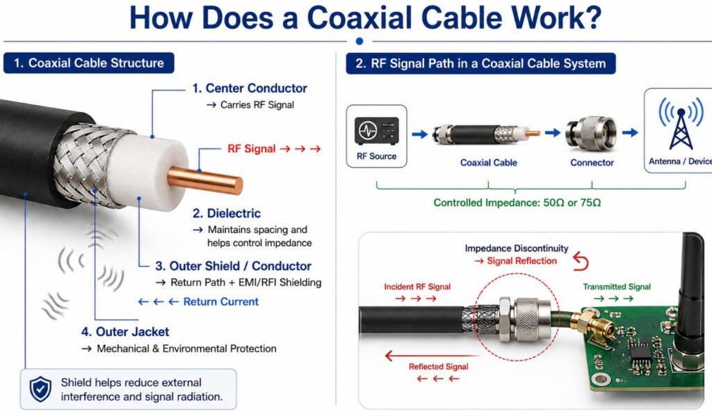
A coaxial cable works by carrying an RF or high-frequency electrical signal through the center conductor while the surrounding outer conductor provides the return path. Together, these two conductors form a controlled coaxial transmission line.
The dielectric keeps the center conductor accurately spaced from the shield, helping maintain the required impedance, typically 50Ω or 75Ω. Proper coaxial cable shielding also reduces external EMI/RFI and limits signal radiation from the cable.
A simple signal path looks like this:
RF Source → Coaxial Cable → Connector → Antenna / Device
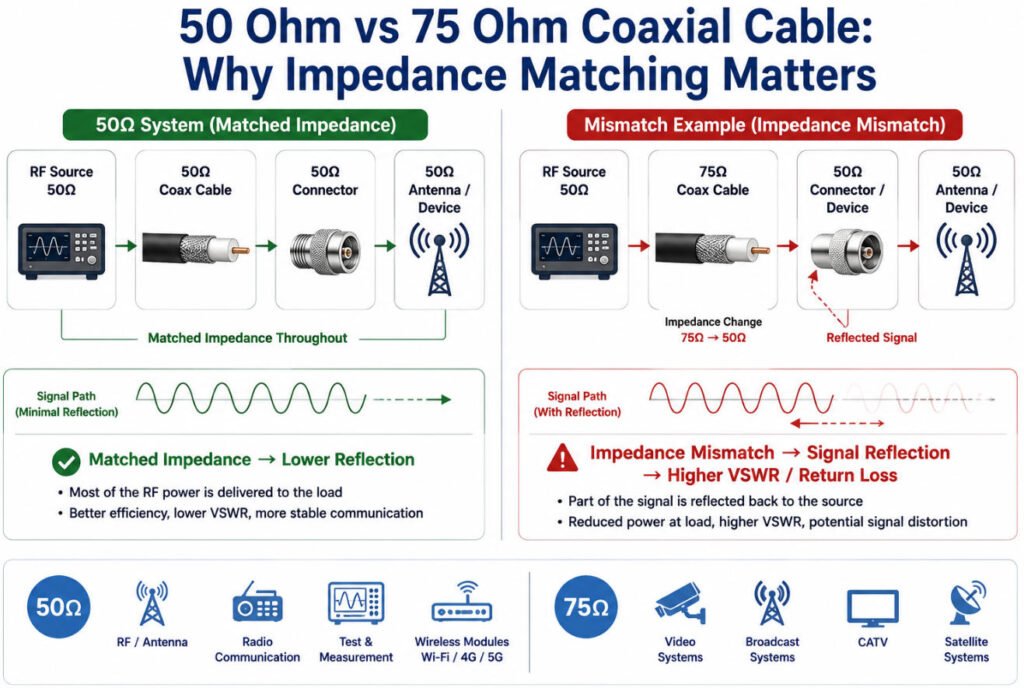
For reliable transmission, the cable, connector, and termination should maintain consistent impedance. Any significant impedance discontinuity can cause part of the coaxial cable signal to reflect back toward the source, increasing return loss and reducing RF performance.
This is why an RF signal cable must be selected and assembled with careful control of impedance, shielding, connector quality, and termination.
What Are the Main Types of Coaxial Cable?
There are seven types of coaxial cable, and they are best classified first by physical construction rather than by RG number. Different designs provide different balances of flexibility, shielding, size, power handling, and RF performance.
In our engineering reviews, we normally select the cable construction first based on routing, frequency, loss, movement, and installation requirements, and then narrow the choice to a specific RF coax cable or manufacturer part number.
1.Flexible Coaxial Cable
Flexible coaxial cable typically uses a stranded or flexible center conductor with a braided outer shield. It is easy to route and is commonly used inside equipment, test systems, antennas, and general RF coax cable assemblies.
2.Semi-Rigid Coaxial Cable
A semi rigid coax cable uses a solid metal outer conductor, which provides stable geometry, strong shielding, and consistent RF performance. However, it has limited flexibility and is normally formed to a fixed shape during installation.
3.Hand-Formable Coaxial Cable
Hand-formable coax provides a compromise between flexible and semi-rigid designs. It can be bent and shaped during installation while maintaining better dimensional stability than conventional flexible coax.
4.Hardline Coaxial Cable
Hardline coaxial cable uses a larger and more rigid outer conductor and is designed for low-loss, high-power transmission. It is commonly used in telecommunications infrastructure, antenna systems, and other long RF transmission paths.
5.Micro-Coaxial Cable
Micro coaxial cable is designed for compact, lightweight, and high-density electronic systems. Its small diameter makes it suitable for cameras, displays, medical electronics, portable devices, and other applications where routing space is limited.
6.Twinaxial Cable
A twinax cable contains two inner conductors inside a common shield and is commonly used for differential signaling. Structurally, it differs from conventional coax, which uses a single center conductor.
7.Triaxial Cable
A triaxial cable adds an additional conductive shield around a conventional coaxial structure. This extra layer can provide improved isolation or guarding for specialized instrumentation, measurement, broadcast, and precision signal applications.
Coaxial Cable Type Comparison
| Type | Flexibility | Shielding | Relative Size | Typical Applications |
|---|---|---|---|---|
| Flexible Coax | High | Braided / foil + braid | Small–Medium | RF assemblies, antennas, test equipment |
| Semi-Rigid Coax | Low | Solid metal outer conductor | Small–Medium | RF and microwave modules |
| Hand-Formable Coax | Medium | Formable metal outer conductor | Small–Medium | RF equipment and internal routing |
| Hardline Coax | Very Low | Rigid metal outer conductor | Large | Telecom, antennas, high-power RF |
| Micro-Coax | High | Miniature shield construction | Very Small | Cameras, displays, compact electronics |
| Twinax | Medium–High | Common outer shield | Varies | Differential data signals |
| Triaxial Cable | Varies | Dual shielding structure | Medium | Precision measurement and instrumentation |
What Are the Most Common RG Coaxial Cable Types?
RG coax cable types are widely used in RF, antenna, communication, video, automotive, test, and industrial applications. Different RG cable types vary in impedance, coaxial cable size, dielectric material, shielding, flexibility, attenuation, and temperature capability.
The table below provides a practical comparison of common RG coaxial cables. Exact specifications vary by construction and manufacturer, so always verify the supplier datasheet before final selection.
| Cable | Impedance | Approx. OD | Relative Loss | Flexibility | Typical Application |
|---|---|---|---|---|---|
| RG58 | 50 Ω | ~5.0 mm | Medium | High | RF, antennas, test cables, radio |
| RG174 | 50 Ω | ~2.8 mm | High | High | GPS, automotive, compact RF assemblies |
| RG178 | 50 Ω | ~1.8 mm | High | High | Compact RF, aerospace, internal equipment |
| RG316 | 50 Ω | ~2.5 mm | Medium-High | High | RF assemblies, test equipment, aerospace |
| RG142 | 50 Ω | ~5.0 mm | Medium-Low | Medium | High-temperature RF and microwave |
| RG400 | 50 Ω | ~5.0 mm | Medium-Low | Medium | Aerospace, military, high-temperature RF |
| RG214 | 50 Ω | ~10.8 mm | Low | Low-Medium | High-power RF and communication systems |
| RG59 | 75 Ω | ~6.1 mm | Medium | High | Video, CCTV, legacy RF systems |
| RG6 | 75 Ω | ~6.9 mm | Low | Medium | CATV, broadband, satellite |
| RG11 | 75 Ω | ~10.3 mm | Lower | Low | Long cable runs, CATV, broadband |
Note: OD and relative loss are typical references only. Actual values depend on the specific cable construction and manufacturer.
Choosing between these RG cable types requires a closer look at their size, flexibility, RF performance, and intended application.
1.RG58 Coaxial Cable
RG58 coax is a 50Ω flexible cable with an OD of approximately 5 mm. It is widely used for RF equipment, antennas, radio, and test cable assemblies.
Selection concern: Check frequency, attenuation, shielding, and cable length, especially for higher-frequency or longer runs.
2.RG174 Coaxial Cable
RG174 coax is a compact 50Ω flexible cable with an OD around 2.8 mm.
Typical applications: GPS, automotive antennas, wireless modules, and compact RF assemblies.
Selection concern: Its small diameter improves routing flexibility but generally results in higher attenuation than larger coax.
3.RG178 Coaxial Cable
RG178 coax is a very small 50Ω cable, typically around 1.8 mm OD, often using a PTFE dielectric.
Typical applications: Aerospace electronics, RF modules, instrumentation, and space-constrained assemblies.
Selection concern: Small dimensions require careful connector termination and process control.
4.RG316 Coaxial Cable
RG316 coax is a flexible 50Ω cable with an OD around 2.5 mm and is commonly selected for RF cable assemblies.
Typical applications: RF equipment, antennas, test systems, aerospace, and instrumentation.
Selection concern: Verify attenuation and connector compatibility for the required operating frequency.
5.RG142 Coaxial Cable
RG142 is a 50Ω coax typically around 5 mm OD with good temperature capability and relatively stable RF performance.
Typical applications: Microwave equipment, aerospace, RF systems, and high-temperature environments.
Selection concern: Larger size and lower flexibility should be considered when routing space is limited.
6.RG400 Coaxial Cable
RG400 coax is a 50Ω high-performance cable commonly used where temperature resistance and strong shielding are required.
Typical applications: Aerospace, military, RF test equipment, communication, and demanding industrial systems.
Selection concern: Higher performance generally comes with higher material cost than general-purpose coax such as RG58.
7.RG214 Coaxial Cable
RG214 is a larger 50Ω coax, typically around 10.8 mm OD, designed for lower loss and higher power handling than many smaller flexible cables.
Typical applications: RF transmitters, communication equipment, antennas, and high-power RF systems.
Selection concern: Its larger diameter increases weight and requires larger connectors and more routing space.
8.RG59 Coaxial Cable
RG59 coax is typically a 75Ω cable with an OD around 6 mm.
Typical applications: Video, CCTV, broadcast, and some legacy RF systems.
Selection concern: For longer or higher-frequency 75Ω runs, lower-loss alternatives may be more appropriate.
9.RG6 Coaxial Cable
RG6 coax is a 75Ω cable widely used for broadband, CATV, satellite, and video transmission.
Typical applications: Television distribution, broadband networks, satellite systems, and building communication infrastructure.
Selection concern: Shield construction and connector compatibility can vary considerably between RG6 products.
10.RG11 Coaxial Cable
RG11 coax is a larger 75Ω cable, typically around 10 mm OD, designed for lower attenuation over longer cable runs.
Typical applications: CATV backbones, broadband distribution, and long-distance video/RF connections.
Selection concern: Lower loss comes with greater size, weight, bend radius, and installation difficulty.
At Yihetai, we recommend confirming the impedance, conductor and dielectric materials, shield construction, cable OD, temperature rating, attenuation requirement, connector type, cable length, and applicable cable datasheet before production.
What Does Coaxial Cable Impedance Mean?
Coaxial cable impedance is the cable’s characteristic impedance for high-frequency signals. It is not the same as DC resistance measured with an ohmmeter. Instead, coax impedance is determined by the geometry and materials of the transmission line.
The main factors include:
- Center conductor diameter
- Distance between the center conductor and shield
- Dielectric material and dielectric constant
- Shield geometry
Common values are 50 ohm coax for RF, wireless, antenna, and test applications, and 75 ohm coax for video, broadcast, and CATV systems.
Maintaining consistent characteristic impedance is important because impedance changes can cause signal reflections, higher VSWR, and degraded RF performance.
How Does Cable Length Affect Coaxial Cable Performance?
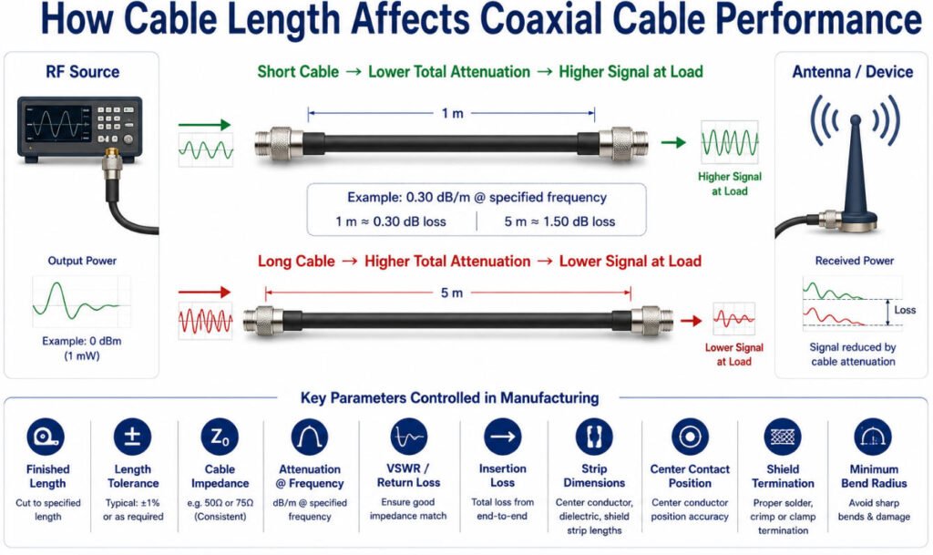
Coaxial cable length directly affects RF performance because attenuation accumulates along the cable:
Longer Cable → More Attenuation → Lower Signal at the Load
This is especially important for antennas, GPS, Wi-Fi, RF test equipment, remote sensors, and other applications where RF cable length can directly affect the available signal level.
For example, if a cable has an attenuation of 0.30 dB/m at the specified operating frequency, a 1 m cable contributes about 0.30 dB of cable loss, while a 5 m cable contributes about 1.50 dB before connector and transition losses are considered.
What Parameters Should Be Controlled in a Coaxial Cable Assembly?
In production, coax cable loss by length is only one part of the specification. Common engineering parameters include:
| Parameter | Why It Matters |
|---|---|
| Finished Cable Length | Determines routing and total RF attenuation |
| Length Tolerance | Ensures repeatable installation and RF path length |
| Cable Impedance | Typically 50Ω or 75Ω depending on the system |
| Attenuation at Specified Frequency | Defines acceptable signal loss |
| VSWR / Return Loss | Checks impedance matching of the finished assembly |
| Insertion Loss | Measures total RF loss through the assembly |
| Cable OD | Affects connector, routing and strain-relief compatibility |
| Minimum Bend Radius | Prevents deformation and RF performance changes |
| Strip Dimensions | Controls the cable-to-connector transition |
| Crimp / Solder Parameters | Affect mechanical retention and RF termination quality |
| Center Contact Position | Helps maintain the intended connector interface geometry |
Is There a Maximum Coaxial Cable Length?
There is no universal coaxial cable maximum length. The acceptable length depends on:
Operating Frequency + Cable Attenuation + Connector Loss + Required Signal Margin
For this reason, engineers selecting coaxial cable length should calculate the complete RF loss budget rather than choosing a maximum distance from a generic chart.
Coaxial vs Twinaxial vs Triaxial Cable: What Is the Difference?
Although coaxial, twinaxial, and triaxial cables are all shielded signal cables, their internal conductor and shield structures are different. Understanding coax vs twinax and coax vs triax is important because these cables are designed for different electrical interfaces and cannot normally be substituted for one another.
Below table for your check:
| Cable Type | Signal Conductors | Shield Structure | Typical Use |
|---|---|---|---|
| Coaxial | 1 | Main outer shield | RF, antenna, video |
| Twinaxial | 2 | Shared outer shield | Differential / high-speed signals |
| Triaxial | 1 | Additional shield layer | Precision / specialized signals |
Coaxial Cable
A standard coaxial cable contains one center signal conductor surrounded by dielectric insulation and an outer conductive shield.
Center Conductor → Dielectric → Shield → Jacket
The center conductor and shield form a controlled-impedance transmission line, commonly 50Ω or 75Ω. Coax is widely used for RF antennas, GPS, radio, CCTV, test equipment, and other high-frequency applications.
Its major engineering requirements include impedance control, attenuation, shielding effectiveness, connector compatibility, and termination quality.
Twinaxial Cable
A twinaxial cable, often called twinax cable, contains two insulated inner conductors inside a common shield.
Conductor A + Conductor B → Dielectric / Filler → Shield → Jacket
The two conductors are commonly used as a balanced or differential pair, making twinax suitable for applications such as:
- High-speed data transmission
- Differential signal links
- Industrial communication
- Data-center interconnects
- Aerospace and electronic systems
The key difference in coaxial vs twinaxial cable is therefore the signal path: coax normally uses one center conductor with the outer conductor as the return path, while twinax uses two inner conductors to carry the differential signal.
For twinax assemblies, engineers also need to control pair geometry, conductor spacing, skew, shielding, and termination symmetry.
Triaxial Cable
A triaxial cable, or triax cable, is structurally similar to coax but includes an additional concentric conductive layer.
A typical construction is:
Center Conductor → Dielectric → Inner Shield → Insulation → Outer Shield → Jacket
The additional shield allows the inner and outer shields to perform different electrical functions depending on the system design. This makes triax useful in specialized applications requiring greater isolation or very low-noise signal transmission, including:
- Precision measurement equipment
- Sensitive instrumentation
- Certain broadcast and camera systems
- Low-current measurement applications
- Specialized laboratory equipment
Compared with standard coax, triaxial cable is generally larger, more complex to terminate, and requires connectors specifically designed for the additional conductor/shield structure.
Coax vs Twinax vs Triax: Which Should You Choose?
The choice should be based primarily on the system interface rather than simply on shielding level.
- Choose coaxial cable for single-ended RF, antenna, video, and other controlled-impedance signals.
- Choose twinax cable when the equipment uses a balanced or differential signal pair.
- Choose triaxial cable when the application requires an additional shield or guard conductor for enhanced isolation or specialized measurement.
What Is a Coaxial Cable Assembly?
A coaxial cable assembly is a finished RF interconnection made from a coaxial cable, one or more RF connectors, controlled termination, strain relief, and required electrical or RF testing.
Coaxial Cable + RF Connector(s) + Termination + Strain Relief + Testing = Coaxial Cable Assembly
Unlike bulk coax cable, which is supplied without terminations, a coax cable assembly is cut to a defined length and terminated with connectors that match the cable, impedance, frequency, and application requirements.
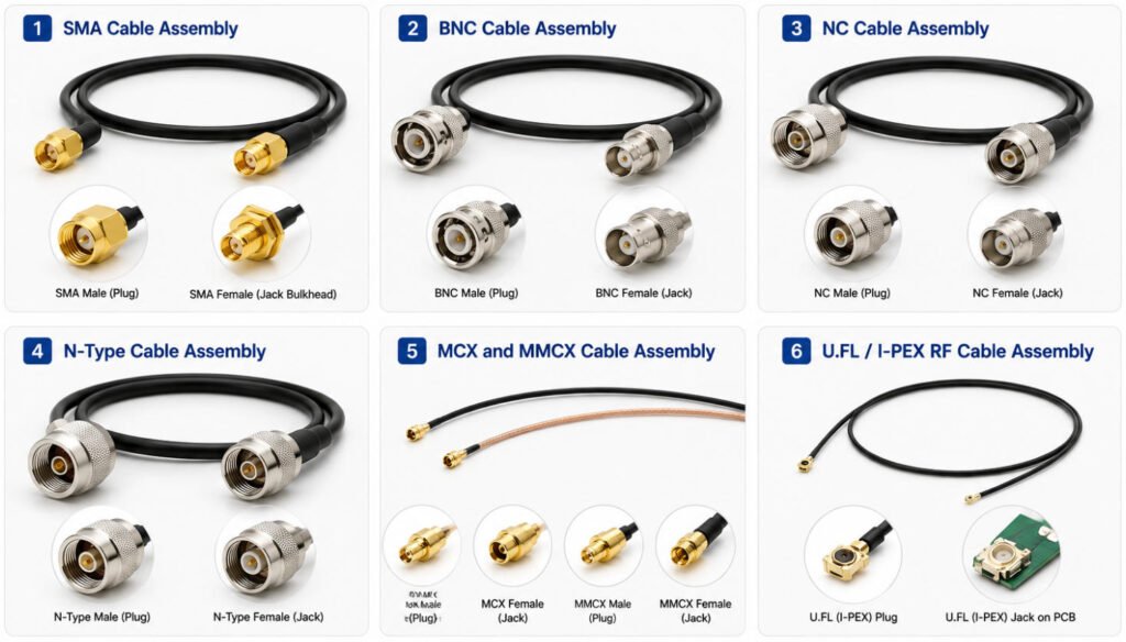
Common configurations include:
SMA Cable Assembly
An SMA cable assembly is widely used in compact RF, antenna, wireless, test, and communication equipment. SMA connectors are threaded and commonly used in 50Ω systems.
BNC Cable Assembly
A BNC cable assembly uses a bayonet-style connector for quick connection and disconnection. It is common in RF test equipment, instrumentation, video, and communication systems.
TNC Cable Assembly
TNC connectors use a threaded coupling and are often selected where better resistance to vibration or accidental disconnection is required.
N-Type Cable Assembly
N-Type assemblies are commonly used in RF infrastructure, antennas, communication equipment, and applications requiring a larger, mechanically robust connector.
MCX and MMCX Cable Assembly
MCX and MMCX cable assembly designs are compact and suitable for space-constrained RF equipment, GPS, antennas, and small electronic devices.
U.FL / I-PEX RF Cable Assembly
U.FL / I-PEX-style assemblies use very small RF connectors, typically with micro-coax cable, for Wi-Fi, Bluetooth, GPS, cellular modules, and compact electronics.
What Are the Most Common Coaxial Cable Connectors?
A coaxial cable connector provides the mechanical and electrical interface between a coax cable and RF equipment. Different coax connector types are designed for different impedance, frequency, size, locking, and environmental requirements, so connector selection should always be matched to both the cable and the application.
Below provides a quick comparison of the most common coaxial cable connectors.
| Connector | Typical Impedance | Relative Size | Typical Applications | Key Advantage |
|---|---|---|---|---|
| SMA | 50Ω | Small | Antennas, GPS, RF modules, test equipment | Compact, threaded connection, high-frequency capability |
| SMB | 50Ω / 75Ω | Small | Automotive, telecom, instrumentation | Quick snap-on connection |
| SMC | 50Ω / 75Ω | Small | RF equipment, instrumentation | Compact threaded connection |
| BNC | 50Ω / 75Ω | Medium | Test equipment, video, instrumentation | Fast bayonet coupling |
| TNC | Typically 50Ω | Medium | Antennas, industrial RF, communication systems | Threaded retention for vibration resistance |
| N-Type | Typically 50Ω; 75Ω versions exist | Large | Base stations, antennas, outdoor RF | Robust construction and higher-power capability |
| F-Type | 75Ω | Medium | CATV, satellite, broadband | Simple, economical 75Ω connection |
| MCX | Typically 50Ω | Small | GPS, automotive, wireless equipment | Compact snap-on interface |
| MMCX | Typically 50Ω | Very Small | GPS, RF modules, portable electronics | Miniature size and rotating snap-on interface |
| U.FL / I-PEX | Typically 50Ω | Ultra-Miniature | Wi-Fi, Bluetooth, GPS, IoT modules | Very small PCB-level RF connection |
How Do You Match a Coaxial Cable With the Right Connector?
Correct coax cable connector selection requires more than checking whether the connector can physically fit the cable. In production, the cable and connector must be treated as one RF transmission system.
Engineers normally verify:
- Impedance — 50Ω or 75Ω must match the system.
- Frequency range — the connector must support the required operating frequency.
- Cable OD — must fit the connector body, ferrule, and strain-relief structure.
- Dielectric OD — affects the cable-to-connector impedance transition.
- Center conductor size — must match the center contact or pin.
- Shield / braid dimensions — must suit the ferrule or shield termination.
- Termination method — crimp, solder, clamp, or compression.
- Connector configuration — straight or right-angle.
- Environmental requirements — temperature, vibration, moisture, corrosion.
- Mating cycles — important for frequently connected RF interfaces.
For example, RF connector datasheets may specify a particular compatible RG cable family, 50Ω or 75Ω impedance, crimp method, operating frequency, and connector orientation. Some N-type connectors are explicitly specified for RG142, RG223, RG400 and similar cables, while other connector families are matched to smaller cables such as RG178.
A connector can mechanically fit a coaxial cable but still be electrically unsuitable for the required frequency or impedance.
In production, we also control strip length, dielectric position, braid preparation, center-contact termination, ferrule crimp dimensions, cable pull force, and finished length tolerance. These small dimensional details can directly affect the RF performance and mechanical reliability of the finished RF cable connector assembly.
What Causes Signal Loss in Coaxial Cable?
Coaxial cable signal loss is mainly caused by attenuation along the cable and additional losses at connectors, terminations, and impedance discontinuities.
A useful rule is:
Higher Frequency + Longer Cable → Generally Higher Attenuation
The main factors affecting coaxial cable loss include:
- Cable length
- Operating frequency
- Conductor resistance
- Dielectric loss
- Cable diameter and construction
- Connector loss
- Impedance mismatch
- Tight bending or poor installation
Larger, well-designed low loss coax cable can reduce attenuation, but the final RF performance still depends on the complete cable assembly.
What Is Coaxial Cable Attenuation?
Coax attenuation is the gradual reduction in signal power as an RF signal travels through the cable. It is commonly specified in dB per unit length at a given frequency, such as dB/100 m or dB/100 ft.
Attenuation generally increases with frequency and cable length, which is why coax cable attenuation should always be checked at the actual operating frequency.
What Is Insertion Loss?
Insertion loss is the total signal loss introduced when a cable assembly is inserted into an RF system. It can include:
- Cable attenuation
- Connector loss
- Termination loss
- Mismatch-related loss
For a finished assembly, RF cable loss is therefore not determined by the bulk cable alone.
What Is the Difference Between 50 Ohm and 75 Ohm Coaxial Cable?
50-ohm and 75-ohm coaxial cables use different characteristic impedances and are generally selected for different RF, data, video, and communication systems. The key difference is not ordinary DC resistance; it is the cable’s characteristic impedance, which must match the connected equipment and RF connectors.
| Feature | 50 Ohm Coax | 75 Ohm Coax |
|---|---|---|
| Typical Applications | RF, antennas, radio, wireless, test equipment | Video, broadcast, CCTV, CATV |
| Common Cables | RG58, RG174, RG316, RG400 | RG59, RG6, RG11 |
| Connector Requirement | 50Ω-compatible connector/interface | 75Ω-compatible connector/interface |
| Main Concern | Impedance matching | Impedance matching |
How Do You Choose the Right Coaxial Cable?
The best coax cable selection starts with the electrical requirements, then moves to mechanical, environmental, connector, and testing requirements. There is no single best coax cable for every application.
A practical coaxial cable selection guide follows this sequence:
- Step 1: Determine Required Impedance:50Ω or 75Ω
- Step 2: Define Operating Frequency
- Step 3: Determine Cable Length
- Step 4: Check Allowable Insertion Loss
- Step 5: Consider Power Handling
- Step 6: Check Cable OD and Routing Space
- Step 7: Check Flexibility and Bend Radius
- Step 8: Define Shielding Requirements
- Step 9: Select Compatible Connectors
- Step 10: Confirm Temperature and Environment
- Step 11: Define Required Testing
How Do You Choose the Right Coaxial Cable Assembly?
Choosing a finished RF cable assembly requires more than selecting the coaxial cable itself. The cable, connectors, length, termination, mechanical design, and RF performance requirements must all be defined as one complete assembly.
Key parameters for coaxial cable assembly selection include:
- Cable Type – such as RG58, RG174, RG316, RG400, or another specified coax
- Connector A – exact connector type and part number
- Connector B – matching equipment interface
- Connector Orientation – straight or right-angle
- Assembly Length – finished end-to-end cable length
- Length Tolerance – allowable production variation
- Frequency Range – required operating band
- Impedance – typically 50Ω or 75Ω
- Insertion Loss Requirement – allowable RF signal loss
- VSWR / Return Loss – required impedance-matching performance
- Bend / Flex Requirement – static routing or repeated movement
- Strain Relief – heat shrink, boot, overmold, or other protection
- Environment – temperature, vibration, moisture, chemicals, sealing
- Testing – continuity, insertion loss, VSWR, return loss, TDR, or mechanical tests as required
A custom coaxial cable or custom RF cable should therefore be specified as a complete coax cable connector assembly, not as separate cable and connector components.
Why Choose Yihetai for Custom Coaxial Cable Assemblies?
For OEM projects, a reliable coaxial cable assembly manufacturer should be able to control not only cable and connector selection, but also stripping, shield preparation, termination, testing, and production consistency. Yihetai supports customized cable and harness projects from engineering review through production.
- 25+ Years of Cable and Harness Manufacturing Experience
- Custom Cable and Connector Configurations
- Prototype to Production Support
- Controlled Cable Preparation and Termination
- Electrical Testing and Traceability
- Automotive and Industrial Manufacturing Experience
- Engineering Support for OEM Projects
Conclusion
Coaxial cables come in many different types, and choosing the right coaxial cable requires more than selecting an RG number. Impedance, operating frequency, attenuation, cable length, shielding, connector compatibility, and environmental conditions should all be considered together.
For a finished coaxial cable assembly, termination quality, strip dimensions, shield preparation, connector installation, and testing also affect RF performance.
If you are developing a custom coaxial cable assembly or RF cable assembly, send Yihetai your drawing, BOM, cable and connector part numbers, or sample for engineering review and quotation from an experienced coaxial cable assembly manufacturer.
Related Wire Harness Articles:
- RG6 vs RG59: Which Coaxial Cable Type Should You Choose?
- Coaxial Cable vs. Twisted Pair Cables: Which One Fits Your Needs?
- Top 5 Things to Know About Coaxial Cables for OEM and Harness Design
- Top 6 Industries That Still Rely on Coaxial Cable in 2026
- Wire Strain Relief Methods: Types, Design, Testing and How to Choose the Right Solution