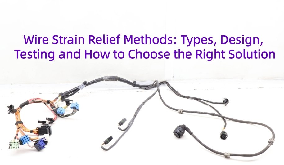
Wire strain relief is a mechanical feature designed to prevent pulling, bending, twisting, or vibration forces from being transferred directly to wires, terminals, solder joints, or connector interfaces. Effective cable strain relief helps reduce conductor fatigue, terminal damage, jacket cracking, and intermittent electrical failures. This blog explains the main wire strain relief methods, how they are designed and tested, and how to choose the right solution for different applications.
What Is Wire Strain Relief?
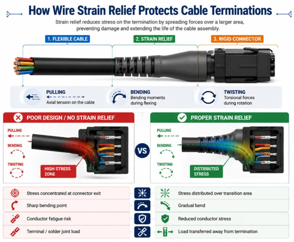
Wire strain relief is a mechanical protection feature designed to reduce stress where a flexible cable or wire meets a rigid connector, enclosure, terminal, or solder point. In a typical cable assembly, the transition looks like this:
Cable → Flexible Section → Strain Relief → Rigid Connector
Without proper cable strain relief, repeated pulling, bending, or twisting can concentrate force at the termination point and eventually cause conductor breakage, loose terminals, cracked insulation, or solder-joint failure.
A well-designed strain relief spreads these forces over a longer section of the cable, moving stress away from the electrical connection and into a controlled flexible transition area. This helps improve mechanical durability, connection reliability, and service life in applications exposed to frequent movement or handling.
Why Is Strain Relief Important in Cable Assemblies?
Strain relief protects more than just the cable from being pulled apart. In a cable assembly, repeated bending, twisting, vibration, or tension can damage the electrical connection long before the cable looks visibly broken.
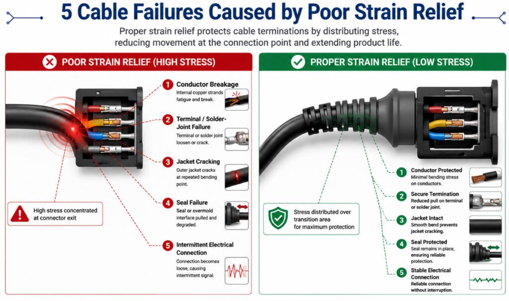
The five most common risks are:
- Conductor Breakage – Repeated flexing can fatigue copper strands near the connector and eventually cause an open circuit.
- Terminal or Solder-Joint Failure – Pulling force can be transferred directly to crimp terminals or solder joints, leading to loosening or cracking.
- Jacket Cracking – Sharp bending at the cable exit can overstress the outer jacket and cause splits or insulation damage.
- Seal Failure – Excessive movement can deform seals or create gaps, reducing waterproof and dust protection.
- Intermittent Electrical Connection – Partial conductor damage or unstable terminals may cause random signal loss, which is often harder to diagnose than a complete failure.
From our manufacturing experience, intermittent failures are among the most difficult problems because the cable may pass a basic continuity test when stationary but fail during movement or vibration.
What Is a Strain Relief Connector?
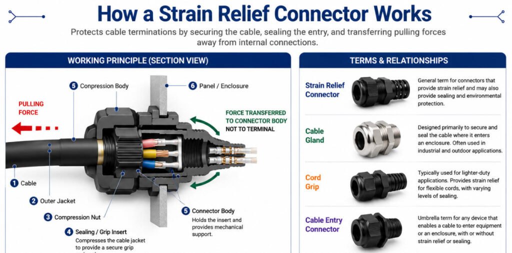
A strain relief connector is a connector or cable-entry component designed to secure a cable and prevent pulling, bending, or twisting forces from reaching the internal terminals, conductors, or solder joints.
In practical terms, a cable strain relief connector grips or supports the cable at the entry point so that mechanical stress is absorbed by the connector body, clamp, gland, or molded section rather than by the electrical connection.
A typical structure is:
Cable → Grip / Sealing Section → Strain Relief Connector → Equipment or Connector Housing
Strain Relief Connector, Cord Grip, and Cable Gland: What Is the Difference?
These terms often overlap in product catalogs and technical searches:
- Strain relief connector: A broad term for components that secure and protect a cable at an entry or connection point.
- Cord grip connector: Usually clamps around the cable jacket to provide retention and strain relief.
- Cable gland connector: Commonly combines cable retention with sealing against dust, moisture, or water.
- Strain relief fitting: A general term for threaded or mounted cable-entry fittings.
- Cable entry connector: Often describes a component that guides, secures, and sometimes seals a cable as it enters an enclosure.
For waterproof applications, a waterproof strain relief connector or cable gland connector normally uses a compression seal around the cable jacket to provide both strain relief and environmental protection.
How Does a Strain Relief Connector Work?
Most designs work by gripping the outer cable jacket and spreading pulling or bending loads over a larger area. This prevents the load from being transferred directly to terminals or solder joints inside the connector.
A properly selected wire strain relief connector should hold the cable securely without crushing the insulation or restricting movement so severely that stress becomes concentrated at another point.
How Do You Size a Strain Relief Connector?
The most important factor is the actual cable outer diameter, not only the conductor size. Buyers should check:
- Cable outside diameter
- Thread or mounting size
- Required pull-out force
- Bend direction
- Sealing requirement
- Temperature and chemical exposure
- Installation space
A cable strain relief fitting that is too large may not grip the cable correctly, while one that is too small can damage the jacket or make installation difficult.
Buyer Note
Do not choose a strain relief connector only by thread size or appearance. At Yihetai, we review cable OD, jacket material, connector geometry, exit direction, sealing requirements, and expected mechanical load before selecting or designing the strain relief solution. For custom applications, a standard fitting may be sufficient, while other projects may require an overmolded or specially designed strain relief.
What Are the Main Wire Strain Relief Methods?
There is no single best wire strain relief method for every cable assembly. The right solution depends on cable diameter, movement, pull force, sealing requirements, connector geometry, environment, and production volume.
The eight most common types of strain relief are compared below.
| Method | Best For | Flexibility | Sealing | Tooling Cost | Typical Applications |
|---|---|---|---|---|---|
| Overmolded Strain Relief | Custom cable assemblies | High | High | Medium–High | Automotive, medical, industrial |
| Cable Gland / Cord Grip | Panel and enclosure entry | Low–Medium | High | Low | Machinery, control cabinets |
| Strain Relief Boot | Connector exits | High | Medium | Low–Medium | Sensors, handheld equipment |
| Strain Relief Grommet | Cable pass-through points | Medium | Medium | Low | Panels, appliances, equipment |
| Strain Relief Clamp | Cable retention | Low | Low | Low | Industrial equipment, internal wiring |
| Heat Shrink Strain Relief | Light-duty reinforcement | Medium | Low | Low | Repair, low-volume assemblies |
| Connector Backshell | Circular and industrial connectors | Medium | Medium | Medium | Industrial systems, complex connectors |
| Spring Strain Relief | Repeated bending | High | Low | Low–Medium | Power tools, movable equipment |
From our manufacturing experience, the best cable strain relief solution is the one that controls stress without simply making the cable exit too rigid. If the relief is too short, too hard, or poorly matched to the cable jacket, the bending stress may simply move to another weak point rather than being reduced.
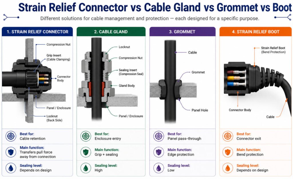
Strain Relief Connector vs Cable Gland vs Grommet vs Boot
These four products are often grouped together because they all protect cables at entry or transition points, but they do not serve exactly the same function. The best choice depends mainly on whether the cable is entering an enclosure, passing through a panel, or exiting a connector.
| Feature | Strain Relief Connector | Cable Gland | Grommet | Strain Relief Boot |
|---|---|---|---|---|
| Primary Function | Secures the cable and reduces mechanical stress at the connection point | Secures and seals a cable where it enters an enclosure | Protects a cable from sharp panel edges and abrasion | Reduces bending stress at the connector exit |
| Typical Location | Connector or enclosure entry | Panel or enclosure entry | Panel hole or pass-through | Cable-to-connector transition |
| Pull Protection | High | High | Low to Medium | Medium |
| Bend Protection | Medium | Low to Medium | Low | High |
| Sealing Capability | Medium to High | High | Low to Medium | Medium |
| Best For | Industrial cable entries, equipment, custom assemblies | Control boxes, outdoor equipment, machinery | Appliances, panels, automotive body openings | USB, data, medical, handheld and overmolded cables |
| Common Related Terms | Cable strain relief fitting, cable entry connector | Cord grip, cable gland connector | Strain relief grommet | Cable strain relief boot, molded boot |
Strain Relief Connector
A strain relief connector is designed to secure the cable while reducing pulling and bending forces at the termination point. It may combine gripping, sealing, and cable-entry functions in one component.
Best choice when: You need both cable retention and controlled stress relief at a connector or enclosure.
Cable Gland
A cable gland is mainly used where a cable enters a panel or enclosure. It grips the cable and often provides sealing against dust, water, and environmental exposure.
Best choice when: The cable enters an electrical box, control cabinet, or outdoor enclosure and sealing is important.
This is why the comparison cable gland vs strain relief is not always about which is better,the two products often solve different problems.
Grommet
A strain relief grommet or cable grommet is installed around a panel opening to prevent the cable jacket from rubbing against sharp edges.
Best choice when: The main concern is abrasion protection at a pass through hole rather than strong cable retention.
A grommet can sometimes provide light strain relief, but it usually does not grip the cable as strongly as a gland or dedicated strain relief fitting.
Strain Relief Boot
A cable strain relief boot is normally positioned where the flexible cable exits a rigid connector. Its purpose is to create a smoother bending transition and prevent the cable from repeatedly bending at one sharp point.
Best choice when: The cable experiences frequent handling, bending, or movement near the connector.
From our manufacturing experience, a common mistake is choosing a cable gland when the real problem is repeated bending at the connector exit, or using a boot when the actual requirement is waterproof cable entry into an enclosure. The correct solution depends first on where the mechanical stress occurs, then on pull force, bend frequency, sealing, and environmental requirements.
How Do You Choose the Right Strain Relief Method?
The right strain relief method depends on how and where the cable will be used. A good wire strain relief selection should consider mechanical stress, bend radius, sealing, installation space, cable diameter, environmental exposure, and production volume.
For many projects, the goal is not to choose the strongest solution, but to choose the most appropriate one for the actual failure risk. To choose the right strain relief method, evaluate the application from both mechanical and manufacturing perspectives. The following seven factors will help you determine the most suitable solution.
1. Identify the Main Mechanical Risk
Start by asking what type of stress the cable will experience:
- Pulling
- Repeated bending
- Twisting
- Vibration
- Abrasion
- Connector movement
For example, a cable gland may be suitable for pull retention, while a boot or spring is usually better for repeated bending.
2. Check the Installation Location
The installation point strongly influences strain relief type selection.
- Panel or enclosure entry: cable gland, cord grip, or grommet
- Connector exit: strain relief boot, backshell, or overmolded strain relief
- Internal harness routing: clamp, clip, or protective sleeve
- Flexible handheld cable: spring, boot, or molded bend relief
3. Consider Cable Diameter and Bend Radius
The strain relief must match the cable diameter and allow an appropriate bend radius.
If the relief is too tight, it can damage the jacket or conductor. If it is too loose, it may not provide enough support.
This is especially important when deciding how to choose a cable gland, because gland size must match the actual cable outer diameter.
4. Determine Sealing Requirements
If the assembly is exposed to water, dust, oil, or chemicals, sealing becomes part of the cable strain relief selection.
Applications requiring environmental protection may use:
- Sealed cable glands
- Overmolded strain relief
- Sealed backshells
- Adhesive-lined heat shrink
The required IP rating or customer specification should be confirmed before selecting the final solution.
5. Evaluate Flexing Frequency
A cable that bends occasionally has different requirements from one that flexes thousands of times during operation.
For frequent flexing, the best cable strain relief is usually one that gradually controls the bend rather than creating a hard transition point.
Common options include:
- Strain relief boots
- Spring strain relief
- Flexible overmolding
6. Consider Space and Assembly Constraints
Some strain relief methods require more installation space than others.
For example:
- Cable glands require panel space and mounting threads
- Backshells add connector length
- Clamps require fixing points
- Overmolding can be optimized for compact custom geometry
For compact OEM products, a custom strain relief design may be more suitable than an off-the-shelf component.
7. Review Production Volume and Tooling Cost
Production quantity also affects the decision.
For prototypes or low-volume projects, standard glands, grommets, clamps, or heat-shrink solutions may be more economical.
For medium or high-volume production, custom cable strain relief or overmolded solutions may justify the initial tooling cost because they can improve consistency, assembly speed, sealing, and appearance.
How Is Strain Relief Designed?
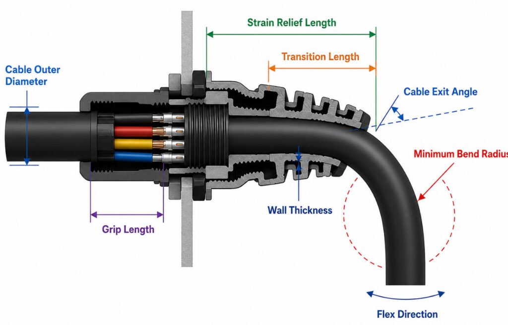
A reliable strain relief design should control bending, pulling, twisting, and vibration at the cable exit without creating a new stress point. In production, engineers normally review the following parameters before finalizing the geometry.
In practical strain relief design, engineers usually focus on the following seven parameters because they directly affect cable retention, bending performance, sealing, durability, and manufacturability.
1.Cable Outer Diameter
The cable outer diameter is the starting point for sizing the strain relief.
Typical manufacturing control:
- Cable OD tolerance should be confirmed from the cable drawing, often within about ±0.1 to ±0.3 mm depending on cable construction.
- The strain relief opening should match the real production OD, not only the nominal value.
If the fit is too loose, retention and sealing may be poor; if too tight, the cable jacket may be damaged.
2.Minimum Bend Radius
The minimum bend radius depends on conductor size, shielding, jacket material, and whether the cable is used in static or dynamic conditions.
Typical engineering practice:
- Static applications may allow a smaller bend radius.
- Dynamic or repeated-flex applications usually require a larger bend radius.
- Always confirm the actual cable supplier specification rather than applying one fixed OD ratio.
3.Strain Relief Length and Transition Length
The strain relief length should spread bending stress gradually away from the connector.
Typical values:
- Small molded cable exits may use a transition length of roughly 15 to 40 mm.
- Larger or more flexible cables may require a longer transition.
The final value depends on cable OD, available space, and flex requirements.
4.Cable Exit Angle
Common cable exit angles include:
- 0° straight
- 45°
- 90°
The exit angle should match the actual routing direction to avoid forcing the cable into a sharp bend after assembly.
5.Material Hardness
For molded strain relief, Shore A hardness is one of the key design parameters.
Typical ranges:
- 60 to 75 Shore A for softer, more flexible strain relief
- 75 to 90 Shore A for stronger mechanical support
Material selection also depends on cable jacket compatibility, temperature, chemical exposure, and sealing requirements.
6.Wall Thickness
For overmolded designs, wall thickness must be sufficient for molding stability while maintaining flexibility.
A typical starting range may be around 1.5 to 3.0 mm, but the final value depends on material flow, geometry, cable size, and tooling design.
7.Tensile and Torsional Load
The strain relief should also be checked against expected mechanical loads such as:
- Pulling force
- Twisting force
- Vibration
- Repeated bending
For OEM projects, these requirements are normally defined by the customer specification or validated through prototype testing rather than using one universal force value.
Manufacturer Insight
In our experience, the most useful cable strain relief design parameters are actual cable OD, minimum bend radius, transition length, exit angle, Shore A hardness, wall thickness, and expected tensile or torsional load. These values should be confirmed with the real cable, connector, and application conditions before tooling or mass production.
What Materials Are Used for Cable Strain Relief?
The most common strain relief materials include PVC, TPE, TPU, silicone, nylon, EPDM, and metal. The right cable strain relief material depends on flexibility, abrasion resistance, sealing, temperature, chemical exposure, and whether the part is molded, assembled, or used as a cable gland.
The table below compares the most common cable strain relief materials by flexibility, durability, processing characteristics, and typical application, making it easier to see which material is better suited to different OEM requirements.
| Material | Key Advantages | Limitations | Typical Applications |
|---|---|---|---|
| PVC | Cost-effective, easy to process, good general-purpose protection | Lower flexibility and temperature performance than some elastomers | Cable overmolding, appliance cables, general electronics |
| TPE | Flexible, good bend performance, suitable for overmolding | Material compatibility must be checked with the cable jacket | Flexible cable assemblies, automotive, industrial equipment |
| TPU | Excellent abrasion resistance, toughness, and mechanical durability | Usually higher cost and may require tighter processing control | Robotics, industrial cables, harsh-environment assemblies |
| Silicone | Very flexible and suitable for wide temperature ranges | Higher material and processing cost | Medical, high-temperature cables, flexible cable boots |
| Nylon | Strong, rigid, wear-resistant, and suitable for threaded parts | Less flexible than elastomer materials | Cable glands, cord grips, mechanical strain relief parts |
| EPDM / Rubber | Good flexibility, sealing, and weather resistance | Material properties vary significantly by formulation | Grommets, boots, outdoor and automotive applications |
| Metal | High mechanical strength, durability, and strong cable retention | Higher weight and cost | Industrial, marine, heavy-duty, and harsh-environment cable glands |
PVC Strain Relief
PVC strain relief is widely used for general-purpose PVC cable overmolding because it is economical, easy to process, and provides good insulation and mechanical protection. It is commonly selected for appliances, consumer electronics, and cost-sensitive cable assemblies.
TPE Strain Relief
TPE strain relief is popular for flexible TPE overmolding because it combines rubber-like flexibility with thermoplastic processing. A TPE cable overmold is often used where repeated bending, soft touch, and strain protection are required.
TPU Strain Relief
TPU strain relief, also referred to as polyurethane strain relief in some applications, offers strong abrasion resistance, tear strength, and durability. TPU overmolding is well suited to cables exposed to frequent movement or mechanical wear.
Silicone Strain Relief
Silicone strain relief provides excellent flexibility and is commonly used where temperature performance or soft bending is important. Typical products include silicone cable overmolding and silicone cable boots for medical, industrial, and high-temperature applications.
Nylon Strain Relief
Nylon strain relief is usually used for harder mechanical components rather than flexible overmolding. It is especially common in nylon cable glands, cord grips, and threaded strain relief components.
EH3:PDM and Rubber Strain Relief
EPDM strain relief and other rubber strain relief solutions provide good flexibility, sealing, and weather resistance. They are commonly used for grommets, boots, and outdoor cable protection.
Metal Cable Glands
A metal cable gland is used when mechanical strength, durability, and environmental protection are more important than flexibility. Common options include stainless steel cable glands and brass cable glands for industrial, marine, and heavy-duty applications.
Which Strain Relief Method Is Best for Different Applications?
Different wire strain relief methods are used depending on cable movement, sealing requirements, connector design, installation space, and production volume. There is no single best solution for every application. The right cable strain relief method should reduce mechanical stress without creating a new bending point or damaging the cable jacket.
The table below compares the most suitable strain relief methods for common cable applications.
| Application | Recommended Method | Why It Fits |
|---|---|---|
| Industrial control cabinet | Cable gland | Provides secure panel entry, cable retention, and optional dust/water sealing |
| Robot / moving equipment | Flexible molded boot | Supports repeated bending and helps control the cable bend radius |
| Medical cable | Smooth molded or overmolded relief | Provides a compact, easy-to-clean transition with controlled flexibility |
| Outdoor equipment | Sealed cable gland or overmold | Helps protect against moisture, dust, and environmental exposure |
| USB / data cable | Molded strain relief boot | Reduces bending stress at the connector exit during repeated handling |
| Automotive sensor cable | Overmolded strain relief | Combines mechanical protection, sealing, and controlled cable routing |
| Power cord | Compression bushing or molded relief | Provides cable retention and reduces pull force at the termination point |
How to Choose the Right Method
For fixed cable entry points, a cable gland is often the most practical solution. For cables that bend repeatedly, a flexible molded boot or overmolded strain relief usually provides better control of the bend area. Where sealing is critical, the strain relief should also be evaluated together with the connector, enclosure, and cable jacket.
Manufacturer Insight
At Yihetai, we usually select strain relief based on the actual application rather than using one method for every cable. A sensor cable, power cord, medical cable, and robotic cable may look similar, but their movement, sealing, and durability requirements are very different.
How Does Overmolded Strain Relief Work?
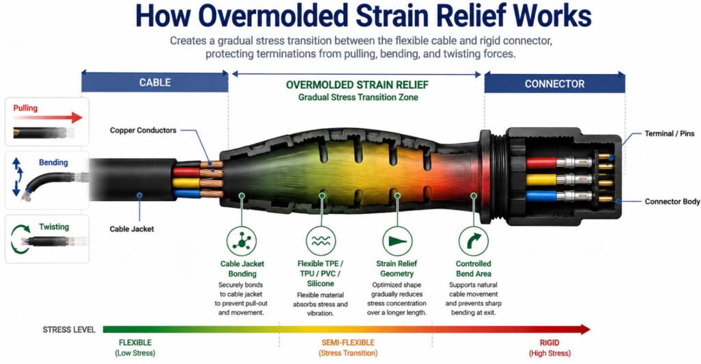
An overmolded strain relief is created by molding a flexible material directly around the transition between a cable and connector. During cable overmolding, the cable and connector are positioned inside a mold, then materials such as TPE, TPU, PVC, or silicone are injected around the termination area to form a controlled flexible section.
The basic structure is:
Cable → Overmolded Strain Relief → Connector
A well-designed overmolded cable strain relief spreads pulling and bending forces over a longer transition instead of allowing stress to concentrate at the terminal, solder joint, or connector exit. This helps improve mechanical durability, sealing, and long-term connection reliability.
For a custom overmolded cable assembly, engineers typically review several 7 keys factors before tooling:
- Cable outer diameter and tolerance
- Cable jacket compatibility
- TPE, TPU, PVC, or silicone overmolding material
- Mold design and insert positioning
- Bonding between the cable jacket and overmold
- Strain relief geometry and exit angle
- Required pull force and bend-cycle performance
In our factory, connector overmolding is commonly used for industrial cables, automotive sensor cables, medical cables, network cables, and other OEM products that require better strain relief, waterproofing, or a customized cable exit.
One common failure we see is choosing an overmolding material that is too hard or does not bond well with the cable jacket. In that case, the molded section may look strong but simply move the bending point farther down the cable. For this reason, custom molded strain relief should be validated through prototype molding, pull testing, bend-cycle testing, and electrical testing before mass production.
Compared with a cable gland, an overmolded strain relief is usually better for integrated connector-to-cable assemblies and repeated bending, while a cable gland is typically better for removable cable entry into a panel or enclosure.
How Is Cable Strain Relief Tested?
Cable strain relief testing is used to verify that the cable, connector, and strain relief can withstand pulling, bending, twisting, and environmental stress without losing mechanical or electrical performance. The exact strain relief test method depends on the application, customer specification, and relevant test standard.
Cable Pull Test
A cable pull test, also called a strain relief pull test or tensile test, applies a controlled axial force to the cable to check whether it slips, separates, or damages the connector interface.
What it verifies: cable retention, bonding strength, and mechanical security.
Bend Cycle Test
A cable flex test or bend cycle test repeatedly bends the cable near the strain relief to simulate long-term use.
What it verifies: fatigue resistance, crack resistance, and whether the strain relief effectively controls bending stress.
Twist and Torsion Test
A twist test or torsion test applies repeated rotational stress to the cable assembly.
What it verifies: resistance to twisting, connector loosening, and internal conductor damage.
Cable and Connector Retention Test
A cable retention test or connector retention test checks whether the cable and connector remain securely assembled under mechanical loading.
Water Ingress and IP Testing
For sealed assemblies, a water ingress test or IP test may be required to verify that the overmold, cable gland, or sealing system prevents moisture from entering the connection area.
Thermal and Chemical Testing
Depending on the application, strain relief assemblies may also undergo thermal cycling and chemical resistance testing to evaluate performance under temperature changes, oils, cleaners, fuels, or other environmental exposure.
Electrical Testing During Flexing
Mechanical testing may be combined with electrical checks such as:
- Continuity during flexing
- Electrical continuity testing
- Insulation resistance
- Contact resistance
This helps detect intermittent electrical failures that may not be visible during static inspection.
Manufacturer Insight
In our production line, strain relief validation typically combines dimensional inspection, pull force testing, bend-cycle testing, and electrical testing. For automotive, medical, outdoor, or other demanding OEM applications, additional environmental testing should be defined according to the customer’s actual operating conditions and test requirements.
How to Specify Strain Relief for a Custom Cable Assembly
To design and quote the right custom cable strain relief, a cable assembly manufacturer needs more than a photo or cable length. Providing clear electrical, mechanical, environmental, and volume requirements helps avoid repeated engineering changes and speeds up prototype development.
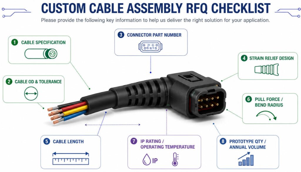
For a custom cable assembly RFQ, provide the following information:
- Cable Assembly Drawing – Overall length, branch dimensions, tolerances, pinout, and strain relief location.
- Cable Specification – Wire/cable type, conductor size, jacket material, voltage rating, and shielding requirements.
- Cable OD – Specify the nominal outer diameter and tolerance, especially for overmolding or sealing.
- Connector Part Number – Provide the exact connector, terminal, and mating information where available.
- Strain Relief Requirements – Specify molded boot, overmolding, cable gland, grommet, or other preferred structure.
- Mechanical Requirements – Include required pull force, bend radius, flex cycles, torsion, or cable retention requirements.
- Environmental Requirements – Provide the IP rating, operating temperature, chemical exposure, UV, oil, or moisture conditions.
- Prototype & Annual Volume – State prototype quantity, expected production quantity, and estimated annual volume so the manufacturer can evaluate tooling and production methods.
Factory Insight: In our engineering reviews, cable OD, jacket material, connector geometry, bend direction, and pull-force requirements are among the most important inputs for a custom overmolded cable assembly. If you already have a cable assembly drawing, BOM, connector part numbers, or physical sample, providing them with the RFQ can significantly reduce design revisions and quotation time.
Why Choose Yihetai for Custom Cable Assemblies with Strain Relief?
Yihetai supports OEM customers that need custom cable assemblies, custom wiring harnesses, and custom molded strain relief solutions from prototype development to volume production.
- 25+ Years of Experience – Long-term experience in custom wire harness and cable assembly manufacturing for OEM projects.
- In-House Overmolding – Support for cable overmolding, connector overmolding, and custom strain relief designs.
- Custom Manufacturing – Build OEM cable assemblies and wiring harnesses according to drawings, samples, connector specifications, and application requirements.
- Prototype to Mass Production – Support prototype cable assemblies, low-volume development, and scalable mass production.
- 100% Electrical Testing – Finished assemblies are electrically tested to verify wiring accuracy and continuity before shipment.
- OEM Engineering Support – Assist with material selection, strain relief geometry, DFM review, testing requirements, and production feasibility.
- Quality Management Systems – Manufacturing processes are supported by ISO and IATF quality management systems for controlled production and traceability.
Yihetai is suitable for OEM customers looking for a custom cable assembly manufacturer or overmolded cable assembly manufacturer that can support flexible development before scaling to production.
Conclusion
Effective wire strain relief protects cables and connectors from pulling, bending, twisting, and repeated movement. The right solution depends on cable OD, bend radius, pull force, operating environment, sealing requirements, and expected flex life.
For OEM projects, strain relief should be designed as part of the complete cable assembly rather than treated as a separate accessory.
If you are developing a custom cable assembly with molded or overmolded strain relief, send Yihetai your drawing, cable specification, connector part number, application requirements, or sample for an engineering review and quotation.
Read more: Wire Strain Relief Methods: Types, Design, Testing and How to Choose the Right SolutionRelated Wire Harness Articles:
- How to Design a Custom Wire Harness for Harsh Environments?
- How to Choose the Right Heat Shrink Tubing for Your Wire Harness?
- What Is a Wiring Harness? A Complete OEM Guide to Types, Components, Manufacturing, Testing and Supplier Selection
- Flat Cable vs Round Cable in Consumer Electronics: Which Is Better for Your Needs?
- Top 20 Custom Cable Assembly Manufacturers in China