The RJ45 color code follows two standard termination schemes: T568A and T568B. T568B uses White/Orange, Orange, White/Green, Blue, White/Blue, Green, White/Brown, and Brown from pins 1 to 8. T568A swaps the orange and green pairs.
Both standards use the same four twisted pairs; the main difference is where the orange and green pairs are terminated.
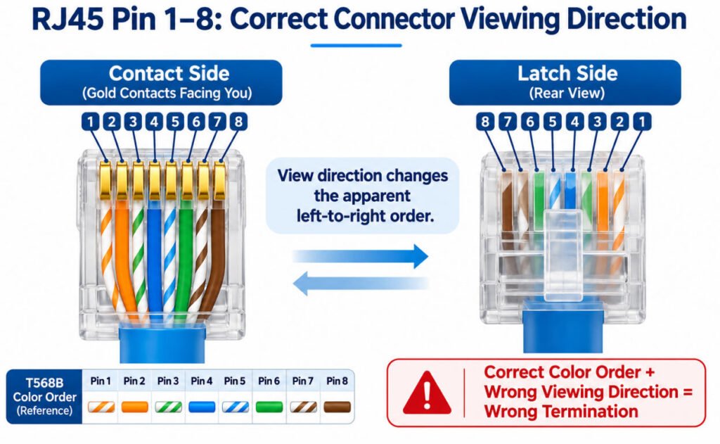
Before reading any RJ45 wiring color code, always confirm the connector viewing direction so the pin numbers are not reversed.
What Is the RJ45 Color Code?
The RJ45 color code defines the order of eight conductors in an Ethernet connector using two standard wiring schemes: T568A and T568B. Both schemes use four twisted pairs but assign the orange and green pairs to different pin positions.
RJ45 Color Code Chart: T568A vs T568B
The following table shows the standard RJ45 wire color order from Pin 1 to Pin 8.
| Pin | T568A Wire Color | T568B Wire Color |
|---|---|---|
| 1 | White/Green | White/Orange |
| 2 | Green | Orange |
| 3 | White/Orange | White/Green |
| 4 | Blue | Blue |
| 5 | White/Blue | White/Blue |
| 6 | Orange | Green |
| 7 | White/Brown | White/Brown |
| 8 | Brown | Brown |
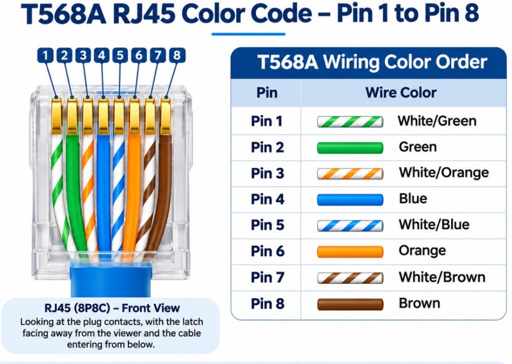
In both wiring schemes, the blue pair remains on pins 4–5, and the brown pair remains on pins 7–8. The main difference is that the orange and green pairs exchange positions between T568A and T568B.
What Is the T568A RJ45 Color Order?
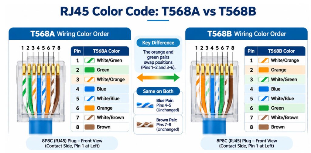
The T568A color order from pin 1 to pin 8 is White/Green, Green, White/Orange, Blue, White/Blue, Orange, White/Brown, and Brown.
The standard T568A RJ45 pinout follows this eight-position wiring sequence:
- Pin 1: White/Green
- Pin 2: Green
- Pin 3: White/Orange
- Pin 4: Blue
- Pin 5: White/Blue
- Pin 6: Orange
- Pin 7: White/Brown
- Pin 8: Brown
The important point is that T568A and T568B do not use different wire colors. They use the same four twisted pairs, but the orange and green pairs occupy different pin positions.
In T568A, the green pair is assigned to pins 1–2, while the orange pair is assigned to pins 3 and 6. The blue pair remains on pins 4–5, and the brown pair remains on pins 7–8.
T568A vs T568B—What Is the Difference?
The main difference between T568A and T568B is the placement of the orange and green twisted pairs. T568A assigns the green pair to Pins 1–2 and the orange pair to Pins 3 and 6, while T568B reverses these assignments. Both use the same eight conductors and support the same Ethernet performance when correctly implemented.
| Item | T568A | T568B |
|---|---|---|
| Pins 1–2 | Green Pair | Orange Pair |
| Pins 3 & 6 | Orange Pair | Green Pair |
| Pins 4–5 | Blue Pair | Blue Pair |
| Pins 7–8 | Brown Pair | Brown Pair |
| Ethernet Performance | Same when correctly implemented | Same when correctly implemented |
As the T568A vs T568B color code comparison shows, only the orange and green pairs exchange pin positions. The blue and brown pairs remain unchanged.
Which Is Better, T568A or T568B?
Neither T568A nor T568B is inherently faster or more resistant to interference.
The choice depends on the existing cabling standard, installation requirements, and applicable project specifications.
For a conventional straight-through Ethernet cable, both ends should use the same wiring scheme: T568A-to-T568A or T568B-to-T568B.
Using T568A on one end and T568B on the other creates a crossover wiring arrangement, which may be appropriate for specific applications but should not be used unintentionally.
How Do You Identify Pins 1–8 on an RJ45 Connector?
To identify RJ45 pins 1–8 correctly, first confirm the connector viewing direction.
An RJ45 plug has two commonly referenced sides:
- Gold-contact side
- Latch side
If you view the plug from the opposite side, the apparent pin sequence is reversed. This is why many RJ45 pin numbering mistakes happen even when the installer remembers the correct T568A or T568B color order.
Before termination, confirm:
- Which side of the connector the drawing shows
- Where RJ45 pin 1 is located
- Whether you are looking at the contact side or latch side
- Whether the manufacturer pinout uses a front, mating, or wire-side view
The safest rule is:
Before reading an RJ45 color code, confirm the connector viewing direction.
Do not rely only on memory or connector appearance. Check the connector manufacturer drawing or the approved RJ45 connector pinout before assigning conductors to pins 1 through 8.
A correct color sequence viewed from the wrong side still produces the wrong termination.
Which RJ45 Color Code Should You Use—T568A or T568B?
Use the wiring scheme specified by the project or existing installation; if no scheme is specified, select one approved scheme and terminate both ends consistently.
When deciding whether to use T568A or T568B, the correct choice depends on the installation requirements rather than personal preference.
How Should You Choose Between T568A and T568B?
Follow this priority order:
- Project Specification: Use the RJ45 wiring standard required by the project documentation or applicable installation specification.
- Existing Infrastructure: Match the established wiring scheme when extending, repairing, or maintaining an existing cabling system.
- Customer Requirement: For OEM cable assemblies, follow the approved customer drawing, pinout, and termination requirements.
- Consistent Termination: Where either scheme is permitted, select one and apply it consistently.
For conventional straight-through Ethernet patch cables, using T568A at both ends or T568B at both ends produces the intended straight-through pin-to-pin wiring.
In our cable assembly engineering work at Yihetai, we recommend verifying the approved pinout rather than relying on wire colors alone. During maintenance, an existing cable should be checked against its documentation or tested wiremap instead of assuming its termination scheme from appearance.
Does T568A or T568B Affect Ethernet Speed?
No. T568A and T568B do not inherently provide different Ethernet speeds when correctly terminated.
The two schemes use the same four twisted pairs and differ only in the position of the orange and green pairs. Neither wiring order is automatically faster or better for Ethernet performance.
Actual network performance depends much more on factors such as:
- Cable category
- Pair integrity
- Cable length
- Termination quality
- Connector performance
- Installation conditions
- Excessive pair untwist
- Damaged or poorly seated conductors
In our experience, speed and link problems are more often caused by termination defects or damaged pair geometry than by choosing T568A instead of T568B.
Why Do Twisted Pairs Matter in RJ45 Wiring?
Twisted pairs matter because Ethernet cables contain four electrically paired conductor sets not eight independent wires. Correct pair assignment helps control crosstalk and maintain reliable signal transmission.
A standard four-pair Ethernet cable contains eight conductors organized into four color-coded twisted pairs:
- Orange Pair: White/Orange and Orange
- Green Pair: White/Green and Green
- Blue Pair: White/Blue and Blue
- Brown Pair: White/Brown and Brown
These RJ45 twisted pairs must remain correctly associated when following the T568A or T568B wiring scheme.
Why Is Twisting Important for Ethernet Signals?
Twisting helps reduce susceptibility to external electromagnetic interference and limits unwanted coupling between adjacent pairs.
Maintaining the correct Ethernet pair assignment is therefore essential for signal integrity, particularly in higher-speed applications.
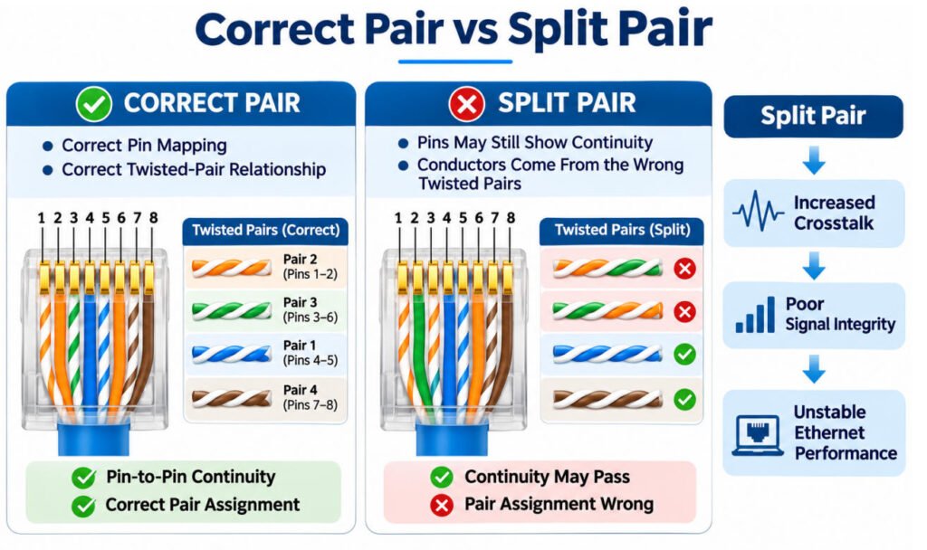
Can an RJ45 Cable Have Correct Pin Continuity but Incorrect Pairing?
Yes. A cable may pass a basic pin-to-pin continuity check while still having incorrect twisted-pair assignments.
For example, individual conductors may connect to the expected pin numbers at both ends, but the wires assigned to a signal pair may come from different physical twisted pairs. This is known as a split pair.
Such wiring errors can increase crosstalk and cause unreliable Ethernet communication.
During termination, avoid excessive untwisting near the connector. Preserve the original pair structure as closely as the applicable connector and cabling specifications require.
What Is a Split Pair in an RJ45 Cable?
What Is a Split Pair in an RJ45 Cable?
A split pair occurs when conductors reach the expected pin numbers but are taken from the wrong twisted pairs.
This is a common RJ45 wiring fault because a basic continuity test may still appear normal:
- Pin 1 connects to Pin 1
- Pin 2 connects to Pin 2
- All eight conductors show continuity
However, the conductors are no longer matched with their correct twisted-pair partners.
For example, instead of keeping one signal pair on two conductors that are physically twisted together, the termination may accidentally combine wires from different pairs.
That creates a problem because Ethernet signaling depends on the electrical relationship within each twisted pair. A split pair can increase crosstalk, disturb impedance balance, reduce signal quality, and cause unstable links or poor network performance.
The key rule is:
A cable can pass a simple continuity check and still fail Ethernet performance because of a split pair.
In production and troubleshooting, this is why a basic pin-to-pin continuity test alone is not enough for Ethernet cable validation.
Straight-Through vs Crossover RJ45 Wiring—What Changes?
A straight-through Ethernet cable uses the same RJ45 wiring scheme at both ends, while a traditional crossover cable uses T568A at one end and T568B at the other. The difference is how the twisted pairs are mapped between the two connectors.
Straight-Through vs Crossover Cable Color Code
| Cable Type | End A | End B |
|---|---|---|
| Straight-Through | T568A | T568A |
| Straight-Through | T568B | T568B |
| Traditional Crossover | T568A | T568B |
How Does Straight-Through Wiring Work?
In RJ45 straight-through wiring, both connectors follow the same termination scheme. Pin 1 connects to Pin 1, Pin 2 to Pin 2, and so on through Pin 8.
Either T568A-to-T568A or T568B-to-T568B provides a standard straight-through connection.
What Changes in a Crossover Cable?
A traditional RJ45 crossover pinout uses T568A at one end and T568B at the other. This exchanges the orange and green pair assignments, crossing the transmit and receive pairs used in conventional 10BASE-T and 100BASE-TX connections.
Historically, crossover cables were used for certain direct connections between similar types of Ethernet equipment.
However, many modern Ethernet devices support Auto-MDI-X, which automatically accommodates the required transmit/receive pair orientation. Therefore, a crossover cable is not mandatory for every direct device-to-device connection.
For legacy equipment or specialized applications, verify the required pinout and device capabilities before selecting the cable.
Do RJ45 Color Codes Change for Gigabit Ethernet?
No. Gigabit Ethernet does not require a different T568A/T568B color code.
The same T568A or T568B wiring scheme is used. What changes is how the Ethernet technology electrically uses the twisted pairs.
For example:
- 10/100BASE-TX traditionally uses two twisted pairs for data transmission.
- 1000BASE-T Gigabit Ethernet uses all four twisted pairs.
This means the blue and brown pairs should not be treated as permanently “unused” simply because older 10/100 Ethernet examples may show data on only two pairs.
For gigabit RJ45 wiring, all four pairs must be correctly terminated and maintain the proper pair relationship.
Does PoE Use a Different RJ45 Color Code?
No. Power over Ethernet does not create a separate T568A or T568B color code. A PoE-enabled Ethernet cable follows the same standard RJ45 wiring color sequence as a non-PoE cable.
The difference is how electrical power is delivered over the existing twisted pairs.
Which RJ45 Pins Are Used for PoE?
A common misconception is that Pins 4, 5, 7, and 8 are always dedicated to PoE power. This is not correct.
Depending on the applicable PoE standard and power-delivery method, power may be supplied through different pair sets:
- Alternative A: Uses the pairs associated with Pins 1–2 and 3–6.
- Alternative B: Uses the pairs associated with Pins 4–5 and 7–8.
- Four-pair PoE: Uses all four twisted pairs to deliver power.
In addition, 1000BASE-T Ethernet uses all four pairs for data transmission. Therefore, the blue and brown pairs should not be treated as permanently reserved for power.
What Should Engineers Check?
For PoE cable assemblies, verify the specified pinout, conductor suitability, connector ratings, and applicable electrical and thermal requirements. Correct color order alone does not establish PoE suitability.
At Yihetai, our engineering approach is to confirm both the Ethernet wiring requirements and the intended power-delivery conditions before approving a cable assembly design.
What Happens If the RJ45 Wire Colors Are in the Wrong Order?
An incorrect RJ45 wire color order can cause communication failures, unstable connections, reduced link speeds, or poor Ethernet performance. The actual result depends on whether the problem affects pin assignments, twisted-pair integrity, or termination quality.
A cable with the wrong RJ45 pinout does not always fail completely. Some wiring defects only become noticeable during higher-speed communication or under network load.
Common RJ45 Wiring Problems and Their Effects
| Wiring Problem | Possible Result |
|---|---|
| Open conductor | No link, reduced negotiated speed, or intermittent connection |
| Wrong pin assignment | Communication failure or incorrect signal mapping |
| T568A on one end / T568B on the other | Traditional crossover mapping; may work with compatible equipment |
| Split pair | Increased crosstalk, unstable links, or reduced performance |
| Poor crimp or contact | Intermittent connection or connection failure |
| Excessive untwist | Higher crosstalk and reduced signal-performance margin |
Why Can an Incorrectly Wired Cable Still Work?
Some Ethernet equipment can accommodate certain transmit/receive pair arrangements through Auto-MDI-X. However, this does not mean that all wiring errors are acceptable.
For example, a split-pair cable may show correct pin-to-pin continuity on a basic tester while failing to maintain the signal integrity required for reliable Ethernet communication.
When troubleshooting RJ45 wiring that is not working, our engineering approach at Yihetai is to verify the connector viewing direction, compare both ends against the approved T568A or T568B pinout, and check the complete wiremap and pair assignments.
Where required, additional transmission-performance testing helps identify defects that continuity testing alone cannot detect.
Why Can an Ethernet Cable Pass Continuity but Still Not Work Properly?
A continuity test confirms an electrical path, but it does not by itself prove correct twisted-pair geometry or full Ethernet transmission performance.
A cable can show end-to-end continuity and still have network problems because Ethernet performance depends on more than whether each conductor is electrically connected.
Possible causes include:
- Split pair — conductors reach the expected pins but come from the wrong twisted pairs.
- Excessive pair untwist — too much untwisting near the connector can increase crosstalk and reduce signal margin.
- Weak termination — poor crimping or unstable contact can cause intermittent communication.
- Damaged conductor — a conductor may still make contact while being mechanically weakened or electrically unstable.
- Connector mismatch — the plug, jack, cable category, or termination method may not be suitable for the application.
- Signal-integrity issue — impedance, crosstalk, return loss, or other transmission characteristics may be outside acceptable limits.
- Installation or environmental issue — tight bends, mechanical stress, EMI, routing near power cables, or harsh operating conditions can affect reliability.
This is why a basic continuity result should not be treated as complete Ethernet qualification.
The practical rule is:
Continuity confirms connection; it does not automatically confirm Ethernet performance.
FAQ
1.Is the RJ45 Color Code the Same for a Plug and a Keystone Jack?
The T568A and T568B pair assignments are the same, but the physical termination layout may look different. RJ45 plugs are terminated by pin position, while keystone jacks often use manufacturer-marked IDC terminals. Always follow the jack’s printed wiring guide and confirm whether you are using T568A or T568B.
2.Is RJ45 the Same as 8P8C?
Not exactly. 8P8C describes an eight-position, eight-contact modular connector configuration. “RJ45” is commonly used in Ethernet applications to refer to the familiar 8P8C modular connector, although the terms are not technically identical.
3.Can I Use T568A on One End and T568B on the Other?
Yes, but doing so creates a traditional crossover wiring arrangement rather than a normal straight-through cable. Whether it works depends on the connected equipment and its Ethernet capabilities. For standard straight-through assemblies, use the same scheme at both ends.
4.Does PoE Use Different Ethernet Wire Colors?
No. PoE does not use a different T568A or T568B color sequence. The same four twisted pairs are terminated according to the selected wiring scheme. PoE changes how the pairs may be electrically used for power delivery, not their conductor colors.
5.Does T568B Support Gigabit Ethernet?
Yes. T568B supports Gigabit Ethernet when the cable, connectors, termination, and complete link meet the required Ethernet specifications. Gigabit Ethernet uses all four twisted pairs, so correct pair assignment and termination quality are important.
6.What Happens If I Reverse the RJ45 Wire Order?
Reversing the wire order can create incorrect pin assignments and may prevent the Ethernet link from working. Depending on the exact error, the cable may show no link, unstable performance, reduced negotiated speed, or other communication problems.
7.Can a Cable Tester Detect a Split Pair?
Some cable testers can detect split pairs, but a simple continuity tester may not. A basic tester may show all eight conductors connected while missing the fact that conductors from different twisted pairs have been incorrectly combined. Continuity alone does not guarantee correct Ethernet pair construction.
8.Is RJ45 the Same as an Ethernet Cable?
No. RJ45 refers to the connector commonly used on twisted-pair Ethernet cabling, while an Ethernet cable is the complete cable assembly. The cable also includes conductors, twisted pairs, insulation, jacket, and potentially shielding in addition to the connectors.
Conclusion
A reliable RJ45 termination should be checked in this order:
Connector View → Pin → Pair → Color → Wiring Standard → Verification
Wire color is only one part of the termination. Correct twisted-pair assignment, pin mapping, connector orientation, and testing are equally important for dependable Ethernet performance.
Do not judge an RJ45 termination by wire color alone. Correct pair assignment, pin mapping, and verification are equally important.
If you are developing a custom RJ45 Ethernet cable assembly, send Yihetai your connector requirements, cable category, pinout, shielding requirement, finished length, application environment, drawing, or existing sample for engineering review and quotation.
Related Wire Harness Articles:
- Shielded Cable Guide: Types, Foil vs Braid, Grounding, EMI Protection & How to Choose
- Coaxial Cable vs. Twisted Pair Cables Which One Fits Your Needs?
- Computer Cable Types: A Complete Guide to PC Cables, Connectors, Ports and Uses
- Top 25 Global Ethernet & RJ45 Cable Manufacturers
- Shielded Twisted Pair vs Coaxial Cable Which Is Best for Your Application?