
A coaxial cable connector terminates a coax cable while maintaining the electrical path, shielding, mechanical connection, and when correctly matched the transmission characteristics required by the system.
Common coaxial cable connectors include SMA, BNC, TNC, N-Type, F-Type, MCX, MMCX, U.FL / I-PEX, and FAKRA. Each connector family differs in size, coupling method, impedance, frequency capability, cable compatibility, and installation method.
In our factory, we do not select coax cable connectors by appearance alone. We check the cable impedance, center-conductor size, dielectric diameter, braid structure, jacket OD, connector termination style, operating frequency, and application environment.
This blog will explains the main RF connectors, how to identify and size them, how they are installed and repaired, and how OEM engineers should match the correct connector to the cable and system requirements.
What Is a Coaxial Cable Connector?
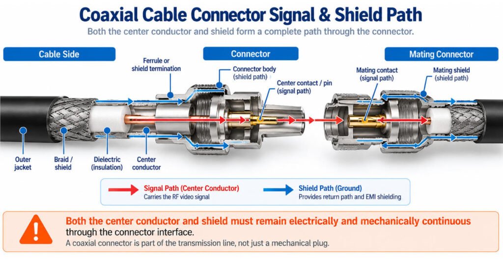
A coaxial cable connector is the interface that terminates a coax cable and transfers the signal into the mating connector while preserving the cable’s conductive and shielding paths.
The signal path is:
Center Conductor → Center Contact → Mating Contact
At the same time, the shielding path is:
Cable Shield → Connector Body → Mating Shield
Both paths matter. If the center contact is poorly terminated, signal loss or intermittent connection can occur. If the braid or shield is not properly captured by the connector body, shielding performance can drop and unwanted interference may increase.
For this reason, a coax connector or RF coax connector should be selected as part of the complete transmission system not simply as a mechanical plug. Cable impedance, dimensions, frequency, and termination method all need to match the connector design.
How Does a Coaxial Connector Work?
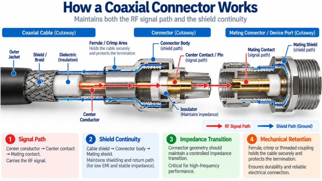
A coaxial connector works by extending the cable’s coaxial structure through the connection without unnecessarily disrupting the signal path.
A typical coax cable is built as:
Center Conductor → Dielectric → Shield → Outer Jacket
At the connector, these layers transition into:
Center Conductor → Center Contact → Mating Contact
Cable Shield → Connector Body → Mating Shield
A good termination therefore has to do more than make electrical contact. It should maintain four things:
Signal Path + Shield Continuity + Controlled Impedance Transition + Mechanical Retention
This is where manufacturing quality becomes important. If too much dielectric is removed, the braid is poorly terminated, the center contact is positioned incorrectly, or the connector is not designed for the cable dimensions, the assembly may introduce an impedance discontinuity or shielding problem.
In our production work, we therefore treat the connector, cable, and termination dimensions as one system. A coax assembly can pass a basic continuity test and still perform poorly at its operating frequency.
Recommended Original Diagram:
Cable Side
Center Conductor
↓
Dielectric
↓
Braid / Foil Shield
↓
Outer Jacket
→ Connector Transition →
Center Contact → Mating Center Contact
Dielectric Support
Connector Body → Mating Outer Contact
What Are the Main Types of Coaxial Cable Connectors?
The main types of coaxial cable connectors differ in coupling style, size, impedance options, and application. Some are designed for TV and broadband systems, some for RF test and wireless, and others for automotive or miniature electronics. Below is a quick comparison table of the most common coaxial cable connectors.
| Connector Type | Typical Coupling | Common Impedance | Typical Applications | Selection Warning |
|---|---|---|---|---|
| F-Type | Threaded | Usually 75Ω | CATV, satellite, broadband | Usually for 75Ω cable systems |
| BNC | Bayonet | 50Ω / 75Ω | CCTV, video, test equipment | 50Ω and 75Ω versions are not the same |
| TNC | Threaded | Usually 50Ω | Wireless, mobile RF, vibration environments | Better vibration retention than BNC |
| SMA | Threaded | Usually 50Ω | Antennas, RF modules, GPS, test | Cable group and center pin dimensions must match |
| RP-SMA | Threaded | Usually 50Ω | Wi-Fi antennas and RF consumer devices | Reverse polarity changes the gender of the center contact |
| N-Type | Threaded | Usually 50Ω, some 75Ω | Base stations, outdoor RF, antennas | Verify frequency, impedance, cable compatibility, and sealing requirements |
| SMB / SMC | Snap-on / Threaded | 50Ω / 75Ω variants | Telecom, instrumentation, compact RF assemblies | Check exact series, coupling style, and impedance |
| MCX / MMCX | Snap-on | 50Ω / 75Ω variants | GPS, compact RF devices, internal assemblies | Small size requires careful cable preparation and handling |
| U.FL / Micro-Coax | Micro snap-on | Usually 50Ω | Wi-Fi modules, IoT boards, internal antennas | Mating cycles, cable strain, and connector fragility must be considered |
| FAKRA / Mini-FAKRA | Locked automotive interface | Usually 50Ω | Automotive RF, cameras, telematics, ADAS | Keying, coding, cable type, and mating compatibility must match |
Common coaxial cable connectors include F-Type, BNC, TNC, SMA, RP-SMA, N-Type, SMB/SMC, MCX/MMCX, U.FL, and FAKRA/Mini-FAKRA. They differ in size, coupling method, impedance, frequency capability, and application.
When selecting a coax connector, always check the specific connector part number and cable compatibility rather than relying on appearance alone.
F-Type Connector
The F-Type connector is a threaded 75 Ω connector commonly used with RG6 and RG59 cables in CATV, satellite, and broadband systems. Compression and crimp versions are available. The connector must match the actual cable dimensions, especially jacket OD and dielectric size.
BNC Connector
The BNC connector uses a quick bayonet coupling and is widely used in video, CCTV, test equipment, and RF systems. Both 50 Ω and 75 Ω versions exist. When selecting BNC, confirm impedance, cable type, and termination dimensions rather than assuming visually similar connectors are interchangeable.
TNC Connector
The TNC connector uses threaded coupling, providing a more secure connection than a bayonet-style interface in vibration-prone applications. It is commonly used in RF, antenna, wireless, and industrial equipment. 50 Ω versions are common, but the exact impedance and frequency rating should be confirmed by part number.
SMA Connector
The SMA connector is a compact threaded 50 Ω RF connector widely used for antennas, GPS, RF modules, communication equipment, and test systems. Selection should specify gender, cable type, straight or right-angle orientation, and frequency requirement—not simply “SMA connector.”
RP-SMA Connector
RP-SMA is a reverse-polarity version commonly found in Wi-Fi and wireless equipment. It can look very similar to standard SMA, but the center-contact arrangement is different. Always check both the threaded interface and center contact before selecting an SMA or RP-SMA assembly.
N-Type Connector
The N-Type connector is a robust threaded RF connector commonly used for antennas, outdoor communication equipment, and higher-power RF systems. 50 Ω versions are common, with 75 Ω variants also available. Cable size, impedance, frequency, and environmental sealing should all be considered during selection.
SMB / SMC Connectors
SMB and SMC connectors provide compact RF connections for communication and electronic equipment. SMB typically uses snap-on coupling, while SMC uses a threaded connection. Different impedance variants are available, so the exact connector series and compatible cable dimensions should be confirmed.
MCX / MMCX Connectors
MCX and MMCX connectors are miniature snap-on RF connectors commonly used in GPS, antennas, wireless modules, and compact electronics. Because of their small size, cable OD, center conductor, dielectric, shield dimensions, and strain relief become particularly important during assembly.
U.FL / Micro-Coax Connectors
U.FL and similar micro-coax connectors are extremely compact interfaces commonly used inside Wi-Fi, GPS, cellular, IoT, and other space-limited electronics. They are typically used with very small coaxial cables, making accurate cable preparation and connector-specific termination tooling especially important.
FAKRA / Mini-FAKRA Connectors
FAKRA and Mini-FAKRA connectors are widely used in automotive antennas, GPS, cameras, telematics, and infotainment systems. Their keyed housings help prevent mating errors. For automotive assemblies, connector coding, cable compatibility, frequency, retention, sealing, and environmental requirements should be confirmed together.
How Do You Identify a Coaxial Cable Connector?
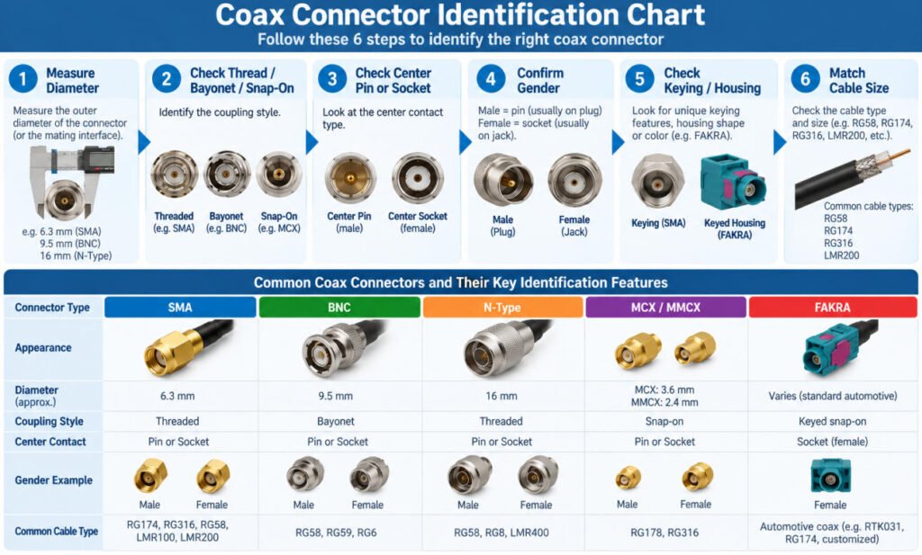
To identify a coax connector, do not rely on its overall appearance alone. Several RF connector families look similar, especially when comparing miniature interfaces.
For practical coax connector identification, check these features in order:
Connector Size → Coupling Method → Center Contact → Gender → Keying → Cable Size
Coax Connector Identification Chart
| Identification Point | What to Check | Why It Matters |
|---|---|---|
| Overall Diameter | Small, medium, or large interface size | Helps narrow down the connector family |
| Coupling Method | Threaded, bayonet, snap-on, or push-on | Helps distinguish BNC, SMA, TNC, SMB, MCX, and other connector types |
| Center Contact | Pin, socket, or reverse-polarity contact | Helps identify connector gender and interface type |
| Gender | Male or female | Confirms mating compatibility |
| Keying / Coding | Standard, reverse polarity, keyed housing, or color coding | Helps prevent mismatching, especially with RP-SMA and FAKRA connectors |
| Cable Size | Cable OD, dielectric OD, and center conductor size | Confirms whether the connector matches the coaxial cable construction |
For example, an SMA connector is small and threaded, a BNC connector uses a bayonet lock, and an MCX connector usually uses a snap-on coupling. FAKRA connectors add a color-coded and keyed housing, while U.FL / micro-coax connectors are extremely small and used for miniature RF cable assemblies.
In production, we do not identify a connector only by its outside shape. We also verify the connector part number, impedance, center-contact style, cable compatibility, and mating requirement.
Male vs Female Coax Connectors: What Is the Difference?
Male and female coaxial cable connectors are defined by their mating interface, but identifying gender is not always as simple as looking for a center pin.
With many standard connector families, a male connector has a center pin and the female connector has a center socket. However, reverse-polarity connectors are an important exception.
That means:
Connector Gender ≠ Always Determined by Center Pin Alone
The outer mating interface and center contact should be checked together.
What Is Reverse Polarity?
Reverse-polarity connectors keep the basic mating interface of the standard connector family but reverse the center-contact configuration.
A common example is SMA vs RP-SMA.
Standard SMA and RP-SMA can look very similar, which makes them easy to confuse when specifying antenna and wireless cable assemblies.
The safest identification method is to check:
Outer Thread → Connector Gender → Center Contact → Manufacturer Part Number
In our factory, we do not approve an RF cable assembly from a description such as “SMA male” based only on a photo. For production, the connector PN, mating interface, cable specification, and polarity should be confirmed before termination.
This small detail can prevent a very expensive mistake: manufacturing a complete batch of coax assemblies that physically look correct but cannot mate with the customer’s equipment.
50 Ohm vs 75 Ohm Coax Connectors
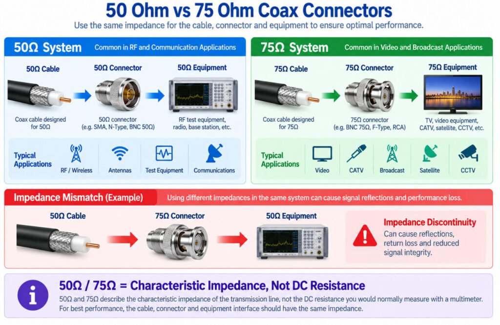
50Ω and 75Ω describe characteristic impedance, not the DC resistance you would normally measure across the cable with a multimeter.
Characteristic impedance is a transmission-line property determined by the geometry and materials of the coaxial structure, including the center conductor, dielectric, shield, and connector transition.
In general:
- 50Ω coax connectors are widely used in RF, wireless, communication, antenna, and test systems.
- 75Ω coax connectors are common in video, CATV, broadcast, and similar signal-distribution systems.
The important rule is:
Cable Impedance → Connector Impedance → Equipment Interface
These should be matched as a system.
For example, a 50Ω cable should normally be terminated with a compatible 50Ω connector and connected to a 50Ω equipment interface. Mixing 50Ω and 75Ω components can create an impedance discontinuity, which may increase reflections and degrade signal performance.
This is especially important with connector families such as BNC, where 50Ω and 75Ω versions can look very similar externally. In RF cable assembly manufacturing, we verify the cable, connector part number, and system impedance together rather than selecting a connector by appearance alone.
How Do You Choose the Right Coaxial Cable Connector?
Choosing the right coaxial cable connector requires more than selecting a familiar connector family. The connector must match the cable, impedance, frequency range, mating interface, termination method, and installation environment.
For OEM applications, the following information should be confirmed before connector selection:
| Requirement | What to Check |
|---|---|
| Cable | RG type or exact cable manufacturer part number |
| Impedance | 50Ω or 75Ω |
| Frequency | Required operating frequency range |
| Interface | BNC, SMA, F-Type, N-Type, TNC, MCX, etc. |
| Gender | Male or female |
| Polarity | Standard or reverse polarity |
| Orientation | Straight or right-angle |
| Termination | Crimp, compression, solder, clamp, or other method |
| Cable OD | Must fit the connector cable-entry range |
| Shield Construction | Braid, foil, double shield, or other structure |
| Environment | Temperature, moisture, vibration, and corrosion exposure |
| Installation | Cable mount, panel mount, bulkhead, PCB, or enclosure interface |
The exact cable dimensions are especially important. Two cables with similar RG designations may still differ in outer diameter, dielectric size, shield construction, or center conductor dimensions, which can affect connector fit and termination.
For RF applications, the complete path should also be considered:
Cable → Connector → Mating Interface → Equipment
For a custom coaxial cable assembly, we prefer to confirm the cable part number and connector manufacturer part number together. This reduces the risk of selecting a connector that mates correctly at the front interface but does not properly fit or terminate the cable at the rear.
What Is a Coax Repair Kit?
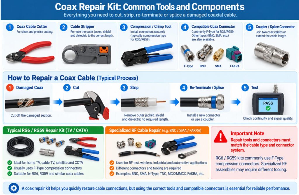
A coax repair kit typically contains the tools and connectors needed to cut, strip, re-terminate, or splice a damaged coaxial cable. These kits are commonly used for RG6, RG59, and similar coax cables in TV, CATV, satellite, and broadband installations.
A typical coaxial cable repair kit may include:
- Coax cable cutter
- Coax stripper
- Compression or crimp tool
- Compatible coax connectors
- F-Type connectors
- Coax couplers or splice adapters
For example, if an F-Type connector is damaged, the old connector can be removed, the cable stripped to the required dimensions, and a new connector installed using the appropriate compression or crimp tool.
However, not every cable should be repaired with a generic coax connector repair kit. The replacement connector must match the cable type, cable OD, dielectric dimensions, shield construction, and impedance.
In our experience, the most important coax cable repair tools are not simply the cutter and crimper the correct stripping dimensions and compatible connector are equally important. A repaired cable may pass continuity testing but still have poor RF performance if the shield, dielectric, or connector transition is incorrectly terminated.
Can a Damaged Coax Connector Be Repaired?
Sometimes, yes. If the damage is limited to the connector end and the remaining coaxial cable is still in good condition, the damaged coax connector can often be removed and replaced with a compatible new connector.
A typical re-termination process is:
Cut Back Damaged Section → Strip to Connector Specification → Prepare Shield → Install New Connector → Inspect → Test
The exact strip dimensions, connector, and termination method must match the specific cable and connector combination. Depending on the design, termination may involve crimping, compression, soldering, or another manufacturer-specified process.
When Should the Coax Cable Be Replaced Instead?
Connector replacement may not be sufficient when the damage extends into the cable itself. Replacement should be considered when there is:
- Severe crushing or flattening
- Water ingress or corrosion
- Badly deformed dielectric
- Significant shield damage
- Multiple damaged sections
- Damage that prevents the required RF performance from being restored
A cable can sometimes pass a basic continuity test while still having structural damage that affects its transmission performance.
For RF and OEM applications, Yihetai evaluates whether the problem is limited to the connector termination or affects the coaxial cable structure itself.
The goal is not simply to restore electrical continuity. The repaired assembly should also maintain proper shield continuity, mechanical retention, termination geometry, and required signal performance.
How Do You Install a Coaxial Cable Connector?
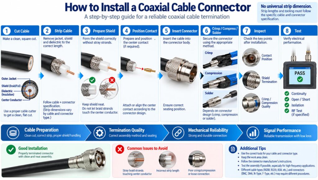
Installing a coaxial cable connector requires controlled cable preparation and a termination process that matches the specific cable and connector design.
A typical manufacturing sequence is:
Cut → Strip → Prepare Shield → Position Contact → Insert Connector → Crimp / Compress / Solder → Inspect → Test
Step1. Cut and Strip the Coax Cable
Cut the cable cleanly and remove the jacket, shield, and dielectric according to the required preparation dimensions.
Strip dimensions must follow the specific cable and connector manufacturer specification.
There is no universal stripping dimension for all coax assemblies. An F-Type connector on RG6, for example, requires different preparation from a BNC on RG59 or an SMA on RG58.
Step2. Prepare the Shield and Center Conductor
The braid, foil, dielectric, and center conductor must be prepared without unintended cuts, loose strands, or excessive deformation. Shield preparation is particularly important for maintaining grounding and shielding continuity.
Step3. Install and Terminate the Connector
Depending on the connector design, the center contact may be crimped or soldered before the connector body is assembled. Other designs use compression or crimp termination directly onto the prepared cable.
The correct tooling should be used for the specified connector and cable combination.
Step4. Inspect and Test the Assembly
After termination, inspect the connector for correct contact position, shield termination, crimp or compression quality, and mechanical retention.
Testing may include:
- Continuity
- Open/short testing
- Conductor-to-shield isolation
- Pull or retention testing
- RF performance testing when specified
For custom coaxial cable assemblies, Yihetai controls cable preparation and connector termination according to the approved cable, connector, drawing, and process requirements.
Small differences in strip length, shield preparation, contact position, crimp geometry, or dielectric condition can affect both mechanical reliability and RF performance. This is why coax connector installation should be treated as a controlled manufacturing process rather than simply attaching a connector to the end of a cable.
What Manufacturing Parameters Matter in a Coax Cable Assembly?
In a coax cable assembly, the connector part number and cable type are only part of the specification. Manufacturing dimensions around stripping, shield preparation, center-contact termination, ferrule compression, and connector seating directly affect mechanical retention and RF performance.
In our factory, we normally control the following parameters according to the approved drawing, connector specification, tooling setup, and customer requirements.
| Process | Parameters We Control |
|---|---|
| Cable Cutting | Finished length, length tolerance |
| Jacket Stripping | Strip length, jacket damage |
| Shield Preparation | Braid exposure, foil condition, braid coverage |
| Dielectric Stripping | Dielectric strip length, center conductor damage |
| Center Contact | Conductor insertion depth, contact position |
| Crimping | Crimp height or crimp diameter where applicable, die/tooling |
| Ferrule | Position, compression, braid capture |
| Connector Assembly | Seating depth, connector orientation |
| Right-Angle Connector | Clocking / orientation |
| Heat Shrink | Position, recovered diameter |
| Pull Test | Cable-to-connector retention |
| Electrical Test | Continuity, open, short |
| RF Test | Defined by frequency, interface, and customer requirement |
The exact control parameters depend on the cable, connector design, termination method, and customer specification. Not every coaxial cable assembly requires every process or test shown above.
Common Coax Termination Problems
In production, many coax termination problems are not caused by the cable or connector itself, but by how the cable is prepared and how the connector is terminated. Below 6 commons problem for you check.
- Braid strands touching the center conductor can create a short between the signal path and shield. Careful shield preparation and visual inspection help prevent stray braid strands from entering the center-contact area.
- A nicked or damaged center conductor can occur during stripping. Even if continuity is initially present, conductor damage can reduce mechanical strength and create a long-term reliability risk.
- Incorrect braid capture under the ferrule can reduce both mechanical retention and shielding effectiveness. The braid must be prepared and positioned according to the specified termination design.
- Incorrect strip length can prevent the center conductor or center contact from reaching its intended position inside the connector. It can also change the geometry of the connector transition.
- Using a connector that does not match the cable OD or cable construction can result in poor retention, improper ferrule compression, or an unreliable termination.
- Combining a 50 Ω cable with an incompatible 75 Ω connector or equipment interface can introduce an impedance discontinuity, even if the components can be physically connected.
How Do You Test a Coaxial Cable and Connector?
Testing a coaxial cable and connector depends on what needs to be verified. Basic electrical testing can identify opens, shorts, and wiring problems, while RF applications may require additional testing to evaluate high-frequency signal performance.
Continuity Test
A basic continuity test checks whether the intended conductive paths are correctly connected and isolated.
For a typical coaxial cable assembly:
Center → Center = Continuity
Shield → Shield = Continuity
Center → Shield = No Short
This testing can identify an open center conductor, interrupted shield path, or an unintended short caused by problems such as stray braid strands touching the center conductor.
However, one distinction is critical:
Passing a continuity test does not prove RF performance.
A coax assembly may have correct DC continuity while still having impedance discontinuities, poor shield termination, connector-transition problems, or other defects that affect performance at the operating frequency.
Can a Multimeter Test a Coaxial Cable?
A multimeter can be useful for checking basic continuity and shorts, but it should not be used to interpret a 50 Ω or 75 Ω coaxial cable rating as ordinary DC resistance.
50 Ω and 75 Ω refer to characteristic impedance, which is a transmission-line property. A basic multimeter does not directly verify the characteristic impedance or RF performance of the finished cable assembly.
RF / High-Frequency Testing
Depending on the RF application and customer specification, additional RF performance testing may be required.
Relevant parameters can include:
| Test Parameter | What It Evaluates |
|---|---|
| Characteristic Impedance | Compatibility with the intended transmission system |
| Insertion Loss | Signal loss through the cable assembly |
| Return Loss | Signal energy reflected by impedance discontinuities |
| VSWR | Degree of impedance mismatch in the RF path |
| Shielding Performance | Effectiveness of the cable and termination against unwanted electromagnetic coupling |
| Frequency Performance | Assembly performance across the specified operating frequency range |
Not every coax cable assembly requires all of these tests. The appropriate test method and acceptance criteria depend on the cable type, connector interface, operating frequency, application, and customer requirements.
Common Coax Connector Problems and Their Causes
A bad coax connector can cause anything from complete signal loss to intermittent or frequency-dependent performance problems. In our manufacturing experience, many coax connector problems are related to cable preparation, shield termination, connector compatibility, or incorrect crimping rather than the connector body itself.
| Problem | Possible Cause |
|---|---|
| No Signal | Open center conductor, wrong connector, or incomplete contact |
| Intermittent Signal | Loose contact, poor termination, or damaged conductor |
| High Signal Loss | Cable damage, connector mismatch, or poor termination |
| Noise / EMI | Poor shield termination or damaged shield |
| Short Circuit | Braid strand touching the center conductor |
| Connector Pulls Off | Incorrect crimp/compression, wrong tooling, or cable mismatch |
| Poor RF Performance | Impedance discontinuity or incorrect termination geometry |
| Corrosion | Moisture ingress, damaged plating, or unsuitable materials |
How Do You Troubleshoot a Coax Connector?
If a coax cable has no signal, start by checking the mating interface, center contact, cable condition, and connector termination. A continuity test can identify an open or short circuit, but it cannot confirm RF performance.
We have seen assemblies that look normal externally but fail because a single braid strand contacts the center conductor or because the braid was not properly captured under the ferrule.
For coax cable repair, the location and severity of the damage matter. A damaged connector end can often be cut back and re-terminated. However, if the cable is crushed, water-damaged, or the dielectric and shield structure have been permanently deformed, replacing the affected cable assembly may be the more reliable solution.
The important point is to identify the root cause before replacing the connector. Installing a new connector will not correct damaged cable geometry, incompatible impedance, or an unsuitable cable-to-connector combination.
What Should OEMs Specify for a Custom Coaxial Cable Assembly?
For a custom coaxial cable assembly, a connector description alone is not enough for engineering review or production.
We sometimes receive RFQs that simply say:
“SMA to BNC cable.”
But that still leaves the cable type, impedance, gender, polarity, orientation, frequency requirement, length, and termination construction undefined.
For a faster and more accurate quotation, OEM customers should ideally provide:
| OEM Information | What We Need to Confirm |
|---|---|
| Cable | Manufacturer + part number |
| Connector A | Manufacturer + part number |
| Connector B | Manufacturer + part number |
| Impedance | 50 Ω or 75 Ω |
| Frequency Range | Required operating frequency |
| Length | Overall length + tolerance |
| Orientation | Straight or right-angle |
| Connector Clocking | Required orientation for angled connectors |
| Environment | Temperature, moisture, vibration, indoor/outdoor use |
| Bend / Flex | Minimum bend requirement or repeated-flex application |
| Shielding | Cable/shield construction requirement |
| Testing | Continuity, open/short, retention, or specified RF tests |
| Annual Volume | Prototype quantity and expected production volume |
A drawing is especially helpful because it can define connector orientation, measurement points, labels, heat shrink, breakout dimensions, and tolerances in one document.
If the exact connector part number is not known, send us the mating interface information, equipment specification, photos, or an existing sample. Our engineering team can then review the cable and connector combination before production.
At Yihetai, we prefer to confirm these details before tooling and first-article production rather than discover a compatibility problem after hundreds or thousands of assemblies have been made.
If you are developing a custom coaxial cable assembly, send us your drawing, cable and connector part numbers, impedance, frequency range, length, environmental requirements, sample, and expected volume for engineering review and quotation.
FAQ
1.What are the most common coaxial cable connectors?
Common coaxial cable connectors include SMA, BNC, TNC, N-Type, F-Type, MCX, MMCX, U.FL / I-PEX, SMB, and RCA, depending on the application, frequency range, impedance, cable size, and environment.
2.How do I know what coax connector I have?
Check the connector shape, coupling method, size, gender, thread type, center contact, and any part markings. For OEM identification, it is better to confirm the manufacturer and part number rather than relying only on appearance.
3.Are all coax connectors the same?
No. Coax connectors differ in impedance, frequency capability, size, coupling style, gender, polarity, cable compatibility, and environmental performance. Two connectors may look similar but still be electrically or mechanically incompatible.
4.What is the difference between 50 ohm and 75 ohm coax connectors?
50 Ω connectors are common in RF, wireless, test, and communication systems, while 75 Ω connectors are common in video, broadcast, and CATV applications. Using mismatched impedance can create reflections and reduce RF performance.
5.What connector is used on RG6 coax cable?
RG6 is commonly used with F-Type connectors in CATV, satellite, and broadband applications, although other connector types may be used if they are specifically designed for the RG6 cable dimensions and application.
6.Can you replace the end of a coaxial cable?
Yes, in many cases the connector can be replaced if the cable itself is still in good condition. The replacement connector must match the cable OD, dielectric size, shield construction, impedance, and termination method.
7.Can you splice a coaxial cable?
Yes, but a splice can introduce additional loss, impedance discontinuity, and shielding changes. For RF applications, a proper coaxial coupler or correctly terminated connector pair is usually preferable to an improvised splice.
8.Does a coax cable pass continuity but still have a bad signal?
Yes. Continuity only confirms the basic conductive path. A coax assembly can pass continuity and still have excessive insertion loss, poor return loss, impedance discontinuity, shielding problems, or connector termination issues at the operating frequency.
In our experience, this is why continuity testing should not be treated as proof of RF performance for high-frequency coaxial cable assemblies.
Related Wire Harness Articles:
- Coaxial Cable Types: A Complete Guide to Impedance, Connectors, RF Performance and Cable Assemblies
- AV Cable Guide: Types, AV InOut, Connectors, Adapters & Custom Design
- Wire Strain Relief Methods: Types, Design, Testing and How to Choose the Right Solution
- Types of Wiring Harnesses in a Car: Complete Guide to Automotive and EV Wiring Harnesses