
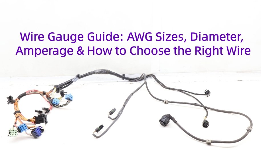
A wire gauge is a standardized way of describing the size of an electrical conductor, including its diameter or cross-sectional area. In practice, electrical wire gauge directly affects current capacity, resistance, voltage drop, flexibility, and heat generation. Common sizing systems include AWG (American Wire Gauge) and metric conductor sizes expressed in mm², while terms such as wire size and cable gauge are often used in product specifications and purchasing documents.
Choosing the correct gauge requires more than matching an AWG number to an amp value. Engineers must also consider conductor material, cable length, ambient temperature, bundling, insulation rating, voltage drop, and whether the wire is used for power, signal, or data transmission.
This blog will explains AWG sizes, wire diameter, amperage, conversions and how to choose the right wire gauge for your application.
What Is Wire Gauge?
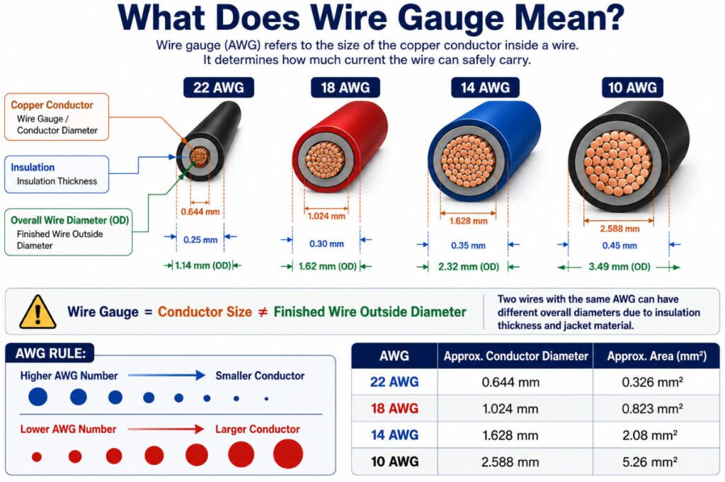
Wire gauge refers to the size of an electrical conductor, usually expressed by its diameter or cross-sectional area. In practical terms, the gauge of cable affects how much current the conductor can carry, how much resistance it has, and how much voltage drop may occur over a given length.
When people ask what is gauge in wire, they are usually referring to conductor size rather than the finished outside diameter of the insulated cable. The insulation and outer jacket can make two wires with the same conductor size look very different.
In North America, AWG (American Wire Gauge) is widely used to define electrical wire gauge. In metric systems, wire size is more commonly specified by conductor cross-sectional area in mm².
In wire harness manufacturing, wire size is normally verified from the approved wire specification and part number rather than by appearance alone. This helps ensure the correct conductor size, insulation type, temperature rating, and electrical performance are used in production.
How Does the AWG Wire Gauge System Work?
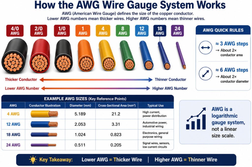
The AWG wire gauge system uses numbers to represent conductor size. Unlike many measurement systems, a lower AWG number means a thicker conductor, while a higher AWG number means a thinner conductor.
For example:
- 40 AWG → very small conductor
- 18 AWG → commonly used for signal and low-current circuits
- 12 AWG → larger conductor used for higher-current power circuits
- 1 AWG → large power conductor
- Larger sizes continue as 1/0, 2/0, 3/0, and 4/0 AWG
A simple way to visualize different gauges of wire is:
4/0 → 3/0 → 2/0 → 1/0 → 1 → 4 → 8 → 12 → 18 → 24
Thicker ←————————————→ Thinner
The important point is that AWG wire sizes are not linear. The difference between two gauge numbers does not represent an equal change in diameter.
As a useful rule of thumb:
- A change of about 3 AWG sizes corresponds to roughly a doubling or halving of conductor cross-sectional area
- A change of about 6 AWG sizes corresponds to roughly a doubling or halving of conductor diameter
This is why the wire gauge difference between 18 AWG and 12 AWG is much greater than the gauge numbers alone may suggest.
For engineers using a wire size guide AWG, it is always better to check the actual conductor diameter, cross-sectional area, resistance, and current requirements rather than relying only on the gauge number.
What Are the Standard AWG Wire Sizes?
A complete wire gauge chart helps engineers compare conductor diameter, cross-sectional area, and resistance across common AWG wire sizes. The table below covers commonly used sizes from 4/0 AWG down to 30 AWG.
| AWG | Diameter (mm) | Diameter (inch) | Cross-Section (mm²) | Approx. Copper Resistance (Ω/km at 20°C) | Typical Application |
|---|---|---|---|---|---|
| 4/0 | 11.684 | 0.46 | 107.2 | 0.161 | Battery cables, high-current power |
| 3/0 | 10.405 | 0.4096 | 85 | 0.203 | EV power, industrial power |
| 2/0 | 9.266 | 0.3648 | 67.4 | 0.256 | Battery, inverter, high-current circuits |
| 1/0 | 8.251 | 0.3249 | 53.5 | 0.323 | Battery and heavy power cables |
| 1 | 7.348 | 0.2893 | 42.4 | 0.407 | High-current equipment |
| 2 | 6.544 | 0.2576 | 33.6 | 0.513 | Battery, motor, industrial power |
| 4 | 5.189 | 0.2043 | 21.2 | 0.815 | Power distribution |
| 6 | 4.115 | 0.162 | 13.3 | 1.3 | Motors, battery connections |
| 8 | 3.264 | 0.1285 | 8.37 | 2.06 | Automotive power, equipment |
| 10 | 2.588 | 0.1019 | 5.26 | 3.28 | Power circuits, appliances |
| 12 | 2.053 | 0.0808 | 3.31 | 5.21 | Power wiring, higher-current circuits |
| 14 | 1.628 | 0.0641 | 2.08 | 8.29 | Lighting, control circuits |
| 16 | 1.291 | 0.0508 | 1.31 | 13.2 | Automotive and industrial wiring |
| 18 | 1.024 | 0.0403 | 0.823 | 21 | Signal, lighting, small loads |
| 20 | 0.812 | 0.032 | 0.518 | 33.3 | Sensors, control circuits |
| 22 | 0.644 | 0.0253 | 0.326 | 53 | Signal and data wiring |
| 24 | 0.511 | 0.0201 | 0.205 | 84.2 | Electronics, communication |
| 26 | 0.405 | 0.0159 | 0.129 | 134 | Fine signal wiring |
| 28 | 0.321 | 0.0126 | 0.081 | 213 | Data, compact electronics |
| 30 | 0.255 | 0.01 | 0.0509 | 339 | Fine electronic connections |
The AWG wire gauge chart shows that as the AWG number increases, conductor diameter and cross-sectional area decrease, while electrical resistance increases. This is why larger conductors are generally preferred for higher-current or longer-distance circuits.
However, the wire size chart should not be used as a universal ampacity table. Actual allowable current depends on insulation temperature rating, ambient temperature, bundling, conductor material, installation method, and the applicable standard.
Complete AWG Wire Gauge Chart
The following wire gauge chart covers standard AWG wire sizes from 4/0 AWG to 40 AWG, including conductor diameter, cross-sectional area, approximate copper resistance, and typical applications.
In the AWG system, a lower gauge number represents a larger conductor. After 1 AWG, larger sizes continue as 1/0, 2/0, 3/0, and 4/0. The values in this AWG chart refer to conductor geometry, not the outside diameter of the finished insulated wire or cable.
| AWG | Diameter (mm) | Diameter (inch) | Area (mm²) | Copper Resistance (Ω/km) | Typical Applications |
|---|---|---|---|---|---|
| 4/0 | 11.684 | 0.46 | 107.2 | 0.161 | Battery, high-current power distribution |
| 3/0 | 10.405 | 0.4096 | 85 | 0.203 | Heavy-duty battery and power cables |
| 2/0 | 9.266 | 0.3648 | 67.4 | 0.256 | High-current automotive and industrial power |
| 1/0 | 8.252 | 0.3249 | 53.5 | 0.322 | Battery and high-power connections |
| 1 | 7.348 | 0.2893 | 42.4 | 0.407 | Heavy power distribution |
| 2 | 6.544 | 0.2576 | 33.6 | 0.513 | Battery and industrial power wiring |
| 3 | 5.827 | 0.2294 | 26.7 | 0.647 | Heavy equipment power wiring |
| 4 | 5.189 | 0.2043 | 21.2 | 0.815 | Automotive battery and power circuits |
| 5 | 4.621 | 0.1819 | 16.8 | 1.03 | Industrial power applications |
| 6 | 4.115 | 0.162 | 13.3 | 1.3 | Battery, charging and power circuits |
| 7 | 3.665 | 0.1443 | 10.5 | 1.63 | Specialized power circuits |
| 8 | 3.264 | 0.1285 | 8.37 | 2.06 | Automotive and equipment power |
| 9 | 2.906 | 0.1144 | 6.63 | 2.6 | Specialized power wiring |
| 10 | 2.588 | 0.1019 | 5.26 | 3.28 | Power and higher-current circuits |
| 11 | 2.305 | 0.0907 | 4.17 | 4.13 | Specialized power and control wiring |
| 12 | 2.053 | 0.0808 | 3.31 | 5.21 | Power circuits and equipment wiring |
| 13 | 1.828 | 0.072 | 2.62 | 6.57 | Specialized automotive and control wiring |
| 14 | 1.628 | 0.0641 | 2.08 | 8.29 | General power and control circuits |
| 15 | 1.45 | 0.0571 | 1.65 | 10.45 | Equipment and control wiring |
| 16 | 1.291 | 0.0508 | 1.31 | 13.17 | Automotive harnesses and appliances |
| 17 | 1.15 | 0.0453 | 1.04 | 16.61 | Specialized control circuits |
| 18 | 1.024 | 0.0403 | 0.823 | 20.95 | Wire harnesses, controls, low-current power |
| 19 | 0.912 | 0.0359 | 0.653 | 26.42 | Control and electronic circuits |
| 20 | 0.812 | 0.032 | 0.518 | 33.31 | Control, signal and electronic wiring |
| 21 | 0.723 | 0.0285 | 0.41 | 42 | Low-current electronics |
| 22 | 0.644 | 0.0253 | 0.326 | 52.96 | Sensors, signals and electronic circuits |
| 23 | 0.573 | 0.0226 | 0.258 | 66.79 | Fine signal wiring |
| 24 | 0.511 | 0.0201 | 0.205 | 84.22 | Data, signal and small electronics |
| 25 | 0.455 | 0.0179 | 0.162 | 106.2 | Fine electronic wiring |
| 26 | 0.405 | 0.0159 | 0.129 | 133.9 | Communication and low-current signals |
| 27 | 0.361 | 0.0142 | 0.102 | 168.9 | Fine signal and electronic circuits |
| 28 | 0.321 | 0.0126 | 0.081 | 212.9 | Electronics and small signal wires |
| 29 | 0.286 | 0.0113 | 0.0642 | 268.5 | Fine electronics |
| 30 | 0.255 | 0.01 | 0.0509 | 338.6 | Fine signal and electronic circuits |
| 31 | 0.227 | 0.00893 | 0.0404 | 426.9 | Miniature electronic wiring |
| 32 | 0.202 | 0.00795 | 0.032 | 538.3 | Electronics and coil wiring |
| 33 | 0.18 | 0.00708 | 0.0254 | 678.8 | Fine coils and miniature electronics |
| 34 | 0.16 | 0.0063 | 0.0201 | 856 | Magnet wire and miniature electronics |
| 35 | 0.143 | 0.00561 | 0.016 | 1,079 | Fine coil and electronic applications |
| 36 | 0.127 | 0.005 | 0.0127 | 1,361 | Magnet wire and micro-electronics |
| 37 | 0.113 | 0.00445 | 0.01 | 1,716 | Very fine winding applications |
| 38 | 0.101 | 0.00397 | 0.00797 | 2,164 | Miniature coils and electronics |
| 39 | 0.0897 | 0.00353 | 0.00632 | 2,729 | Very fine magnet wire |
| 40 | 0.0799 | 0.00314 | 0.00501 | 3,441 | Micro-coils and extremely fine electronics |
The wire diameter chart above provides a useful reference for comparing cable gauge sizes, conductor area, and wire gauge thickness. However, AWG size alone does not determine how much electrical current a wire can safely carry.
Important: Wire gauge does not have one universal ampacity value. Allowable current depends on insulation temperature rating, ambient temperature, conductor material, bundling, installation method, duty cycle, applicable standards, and permitted voltage drop.
What Is the Difference Between Wire Gauge, Diameter and Cross-Sectional Area?
Wire gauge, conductor diameter, cross-sectional area, and finished cable OD are related measurements, but they describe different parts of a wire. Understanding the difference is especially important in OEM wire harness design because electrical sizing and connector compatibility often depend on different dimensions.
Wire Gauge vs Diameter vs Cross-Sectional Area
| Parameter | What It Means | Unit |
|---|---|---|
| AWG | Standard conductor size designation | Gauge number |
| Conductor Diameter | Physical diameter of the conductor | mm / inch |
| Cross-Sectional Area | Conductive area of the conductor | mm² |
| Finished Wire OD | Outside diameter including conductor and insulation | mm |
In a wire gauge vs diameter comparison, AWG is the standardized size designation, while wire diameter is the physical conductor diameter associated with that gauge. The wire cross sectional area describes how much conductive material is present and is normally expressed in mm².
The important point is that wire gauge thickness does not equal finished cable diameter. For example, the AWG diameter of a 12 AWG conductor refers to the conductor itself, not the total outside diameter after insulation is added.
So:
12 AWG conductor diameter ≠ 12 AWG finished cable diameter
This distinction between cable diameter vs wire gauge is important for OEM engineers because connector seals, terminals, cable glands, protective tubing, and overmolding designs may all depend on the actual outside diameter of the insulated wire.
At Yihetai,in our wire harness production, we verify both conductor size and finished wire OD because the terminal may be selected by conductor range while the connector seal is selected by insulation diameter.
AWG to mm²: How Do You Convert Wire Gauge to Metric Size?
AWG to mm² conversion is used to compare American Wire Gauge sizes with metric conductor sizes. AWG identifies conductor size using a gauge number, while metric systems usually specify conductor cross-sectional area in mm².
The conversion is useful for engineering and sourcing, but it is important to understand that an AWG value and a commercial metric wire size are not always exact product equivalents. The calculated cross-sectional area may fall between commonly available metric cable sizes.
AWG to mm² Conversion Chart
| AWG | Approx. Cross-Section |
|---|---|
| 24 | 0.20 mm² |
| 22 | 0.33 mm² |
| 20 | 0.52 mm² |
| 18 | 0.82 mm² |
| 16 | 1.31 mm² |
| 14 | 2.08 mm² |
| 12 | 3.31 mm² |
| 10 | 5.26 mm² |
| 8 | 8.37 mm² |
| 6 | 13.3 mm² |
| 4 | 21.2 mm² |
| 2 | 33.6 mm² |
| 1 | 42.4 mm² |
| 1/0 | 53.5 mm² |
| 2/0 | 67.4 mm² |
| 3/0 | 85.0 mm² |
| 4/0 | 107.2 mm² |
This AWG mm² chart is useful for quick wire gauge to mm² comparison, but the nearest commercial metric cable size may be slightly different.
Is AWG the Same as mm²?
No. AWG and mm² are two different wire sizing systems.
AWG is a standardized gauge system based on conductor diameter, while mm² directly expresses conductor cross-sectional area.
For example:
- 18 AWG ≈ 0.82 mm²
- 14 AWG ≈ 2.08 mm²
- 10 AWG ≈ 5.26 mm²
However, common metric cable sizes may be sold as:
- 0.75 mm²
- 1.0 mm²
- 1.5 mm²
- 2.5 mm²
- 4.0 mm²
- 6.0 mm²
So a wire gauge to mm or mm² to AWG conversion should be treated as a technical comparison, not an automatic substitution.
For OEM and wire harness projects, engineers should also verify current rating, conductor resistance, terminal compatibility, insulation OD, temperature rating, and applicable standards before replacing an AWG wire with a metric size.
AWG vs SWG: Are They the Same?
No. AWG and SWG are different wire gauge systems, and the same gauge number does not represent the same conductor diameter in both systems.
AWG stands for American Wire Gauge and is widely used in North America for electrical conductors and cables.
SWG stands for Standard Wire Gauge and is an older gauge system historically used in the United Kingdom and some other markets.
For example, an 18 AWG conductor and an 18 SWG conductor do not have the same diameter. This means AWG and SWG wire gauge values should never be treated as interchangeable.
| Gauge System | Full Name | Common Use | Same Number = Same Diameter? |
|---|---|---|---|
| AWG | American Wire Gauge | Electrical wire and cable, especially in North America | No |
| SWG | Standard Wire Gauge | Historical UK and general wire sizing applications | No |
For engineering drawings, BOMs, and cable specifications, always state the exact wire gauge system being used. Writing only “18 gauge” can create sourcing and manufacturing errors if the supplier does not know whether it means AWG or standard wire gauge.
What Is the Diameter of 4/0 AWG Wire?
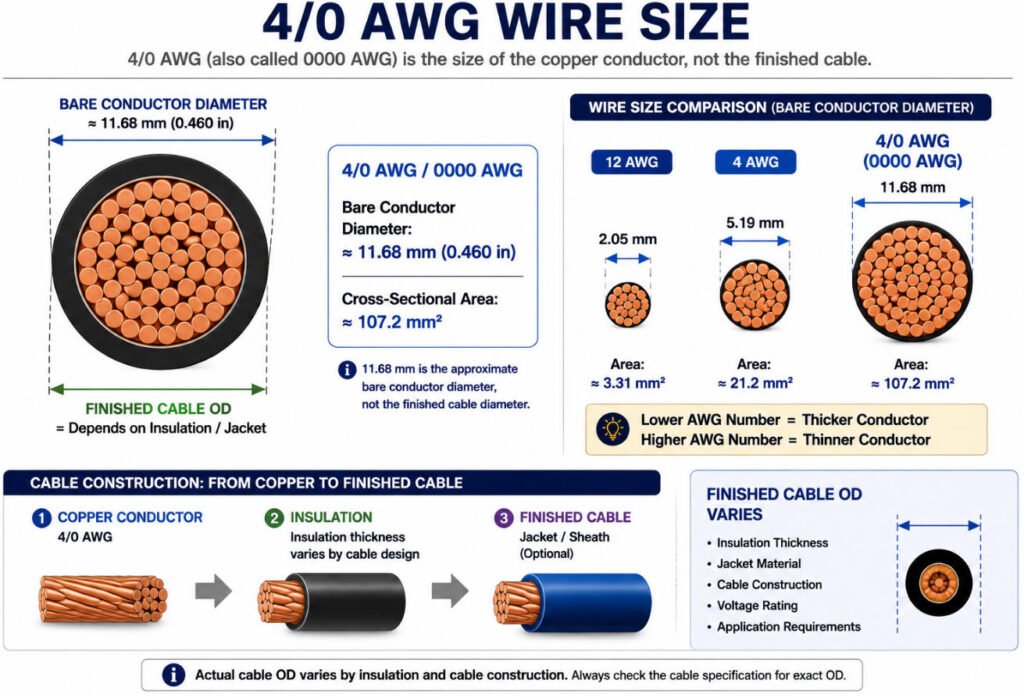
The 4/0 AWG wire diameter is approximately 11.68 mm (0.460 inch) for a bare conductor, with a cross-sectional area of approximately 107.2 mm².
4/0 AWG, also written as 0000 AWG, is one of the largest standard sizes in the American Wire Gauge system. When asking what does 4/0 AWG mean, it refers to the conductor size rather than the outside diameter of the finished insulated cable.
| Parameter | 4/0 AWG Size |
|---|---|
| Bare Conductor Diameter | Approx. 11.68 mm / 0.460 in |
| Cross-Sectional Area | Approx. 107.2 mm² |
The actual 4/0 cable diameter will be larger because insulation, shielding, and outer jackets add thickness. Therefore, for connector or cable assembly design, always check the manufacturer’s finished cable OD specification rather than relying only on the 4/0 wire size.
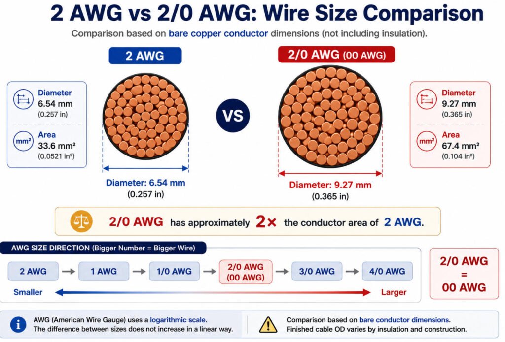
What Is the Difference Between 2 AWG and 2/0 AWG?
2 AWG and 2/0 AWG are not the same size; 2/0 AWG is significantly larger. In the American Wire Gauge system, 2 AWG wire size has a conductor diameter of about 6.54 mm and a cross-sectional area of approximately 33.6 mm², while 2/0 AWG is about 9.27 mm in diameter with an area of approximately 67.4 mm².
| Feature | 2 AWG | 2/0 AWG |
|---|---|---|
| Diameter | 6.54 mm | 9.27 mm |
| Cross-Sectional Area | 33.6 mm² | 67.4mm² |
| Relative Size | Smaller | Larger |
The 2/0 AWG meaning is the same as 00 AWG. These larger aught wire sizes continue in this order:
1/0 → 2/0 → 3/0 → 4/0
Each step represents a progressively larger conductor.
So, in a 2 AWG vs 2/0 or 2 gauge vs 2/0 comparison, 2/0 has roughly twice the conductor cross-sectional area of 2 AWG. If you are asking what does 2/0 wire mean, it refers to a large AWG conductor commonly used where higher current capacity and lower resistance are required.
How Do You Determine the Gauge of a Wire?
If you are trying to understand how to know wire gauge, the best approach is to follow a practical sequence: first check the wire marking, then measure the bare conductor if needed, and finally compare the result with a reliable AWG reference chart.
1.Check the Wire Marking
The easiest way to determine wire gauge is to read the marking printed on the insulation or cable jacket.
Common examples include:
- 18 AWG
- 12 AWG
- 2.5 mm²
If the marking is clear, this is normally more reliable than estimating wire size by appearance.
2.Measure the Bare Conductor Diameter
If the marking is missing or unreadable, carefully remove the insulation and perform a wire gauge measurement on the conductor itself.
Common tools include:
- Micrometer
- Caliper
- Wire gauge tool
A micrometer usually gives the most precise diameter measurement for a solid conductor.
3.Compare With an AWG Chart
After measuring the bare conductor diameter, compare the result with an AWG wire size chart to find the closest standard gauge.
For example, if the conductor diameter is close to 1.02 mm, it corresponds approximately to 18 AWG.
This is a practical method for how to measure wire gauge when no specification or marking is available.
4.Be Careful With Stranded Wire
Stranded wire requires more care because the outside diameter of the strand bundle is not the same as the nominal solid-conductor diameter listed in a standard AWG chart.
Do not determine AWG from the insulation outside diameter alone. Insulation thickness can vary significantly between different wire types, even when the conductor gauge is the same.
For stranded conductors, engineers may also need to verify:
- Strand count
- Individual strand diameter
- Total conductor cross-sectional area
- DC resistance
- Insulation OD
In our factory, wire size is checked together with strand construction, conductor diameter, DC resistance, and insulation OD rather than relying on cable OD alone.
Wire Gauge vs Amperage: How Are They Related?
Wire gauge vs amperage is closely related because thicker conductors usually have lower resistance and can carry more current. However, wire ampacity is not determined by AWG size alone.
The actual current carrying capacity also depends on:
- Conductor material
- Insulation temperature rating
- Ambient temperature
- Bundling
- Installation method
- Applicable standards
Does Thicker Wire Carry More Current?
In general, yes. A larger conductor usually carries more current with less resistance and voltage drop.
Why Doesn’t One AWG Size Have One Fixed Amp Rating?
The same AWG size can have different wire gauge amps depending on temperature, insulation, bundle size, and installation conditions. That is why a wire gauge amp chart should only be used as a reference.
What Causes a Wire to Overheat?
Common causes include excessive current, undersized conductors, high ambient temperature, poor heat dissipation, and high-resistance terminals or crimps.
In harness production, we do not approve a wire size for amps based only on an online chart. Temperature, bundle size, run length, terminal rating, and application standards must also be reviewed.
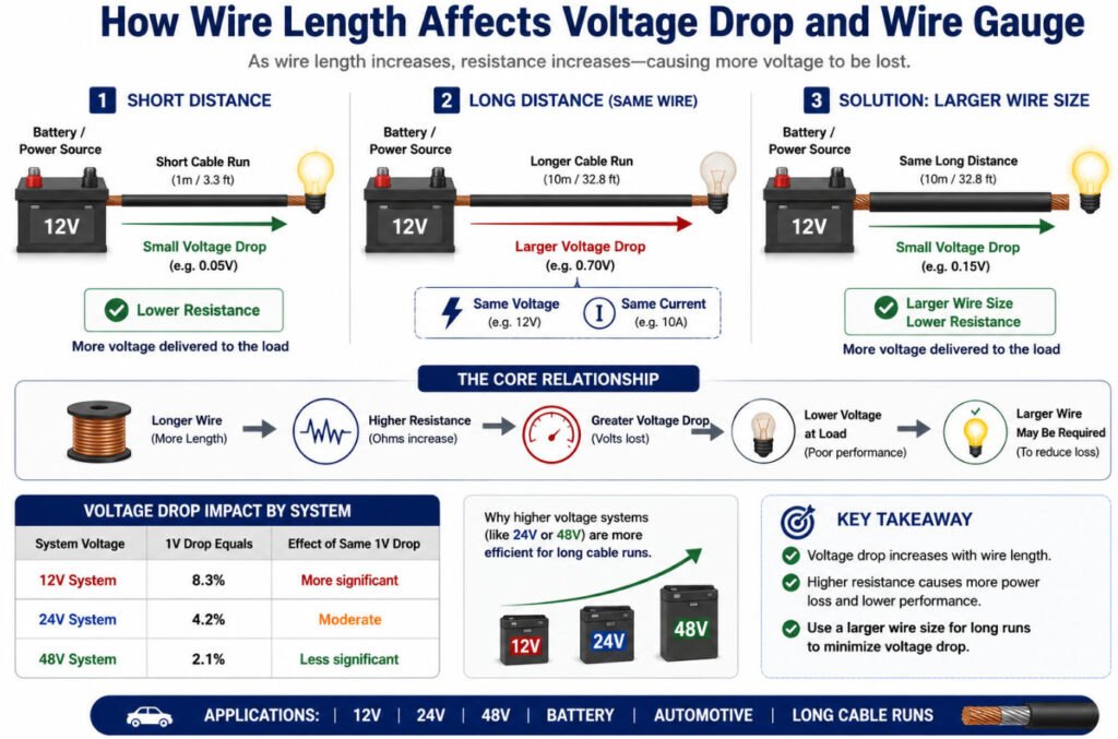
How Does Wire Length Affect Wire Gauge and Voltage Drop?
How Does Wire Length Affect Wire Gauge and Voltage Drop?
Wire length directly affects electrical resistance and voltage drop:
Longer Wire → Higher Resistance → Greater Voltage Drop
Even when a wire has sufficient ampacity, a longer cable run may still require a larger conductor to keep voltage drop within an acceptable range. This is especially important when selecting wire gauge by length for 12V, 24V, 48V, battery, and automotive systems.
Why Does a Longer Cable Need a Larger Wire Size?
As cable length increases, total resistance increases. A larger conductor has lower resistance, so increasing voltage drop wire size can help reduce energy loss and maintain the required voltage at the load.
This is why wire size for distance should be considered together with current, not separately.
Why Is Voltage Drop Important in 12V and 24V Systems?
Voltage drop is especially important in low-voltage DC systems because even a small voltage loss can represent a significant percentage of the supply voltage.
For example, 12V wire gauge and 24V wire gauge selection often depends heavily on cable length, while 48V wire gauge may allow more flexibility for the same power level.
Typical applications include:
- Battery cables
- Automotive wiring harnesses
- Long cable runs
- Motors and pumps
- DC power distribution
For DC wire size selection, we review current, cable length, allowable voltage drop, temperature, and terminal resistance together rather than choosing wire gauge from ampacity alone.
Does Stranded Wire Use the Same Gauge as Solid Wire?
Yes. Solid and stranded wire can use the same nominal AWG size, but the finished physical dimensions may not be identical.
In a solid vs stranded wire comparison, a solid conductor is one continuous piece of metal, while a stranded conductor is made from multiple smaller strands. The final stranded wire diameter can vary depending on:
- Wire strand count
- Individual strand diameter
- Conductor class
- Compacted or non-compacted construction
- Required flexibility
This means two AWG stranded wire products with the same nominal gauge may still have different conductor geometry or insulation OD.
For flexible applications, manufacturers may use finer strand counts to improve bend performance, so flexible wire gauge selection should consider more than AWG alone.
In wire harness production, stranded construction matters because it affects:
- Crimp barrel compatibility
- Connector seal fit
- Connector cavity size
- Finished insulation OD
- Flex life
For this reason, we verify the approved wire specification, strand construction, conductor size, and insulation OD before selecting terminals and seals rather than relying only on the nominal stranded wire gauge.
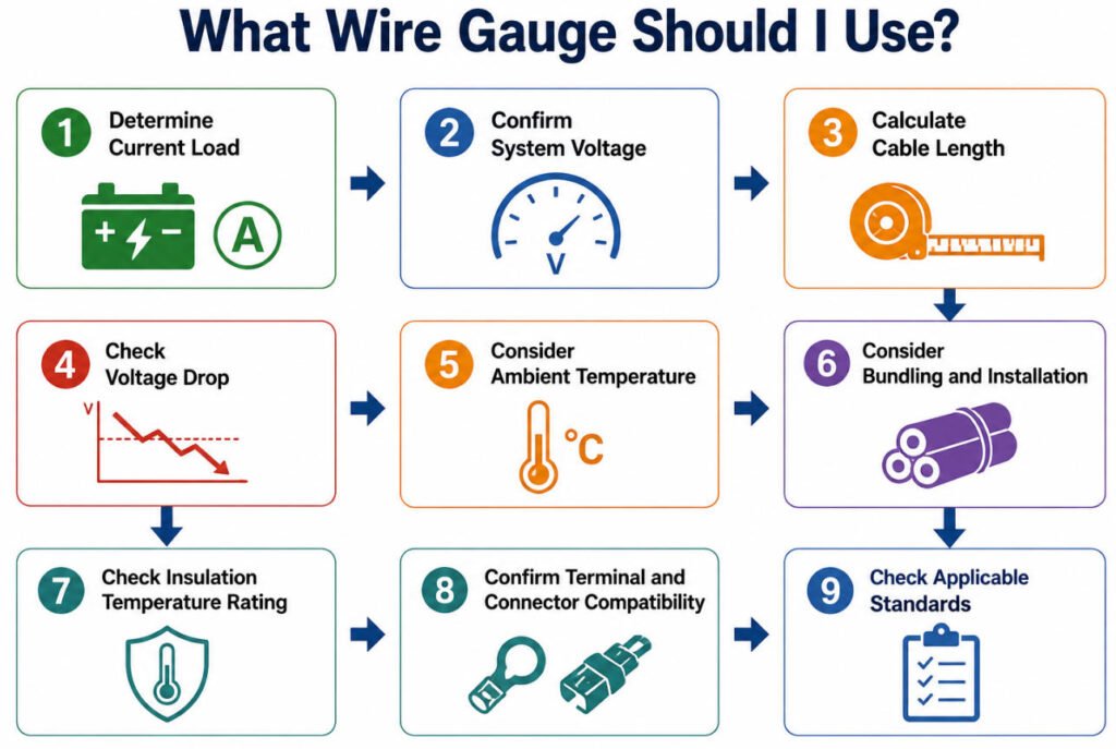
What Wire Gauge Should I Use?
There is no single wire gauge that is correct for every application. Wire gauge selection should be based on current, voltage, cable length, temperature, installation conditions, connector limits, and applicable standards.
A practical electrical wire sizing process is:
Step 1: Determine Current Load
Start with the maximum continuous and peak current the circuit is expected to carry. Higher current generally requires a larger conductor.
Step 2: Confirm System Voltage
Identify whether the system operates at 12V, 24V, 48V, or another voltage. Lower-voltage systems are often more sensitive to voltage drop.
Step 3: Calculate Cable Length
Longer cable runs have higher resistance, so wire size selection should account for total circuit length.
Step 4: Check Voltage Drop
Even if ampacity is acceptable, voltage drop may require a larger wire size. This is especially important in DC, battery, and automotive circuits.
Step 5: Consider Ambient Temperature
Higher temperatures reduce allowable current carrying capacity and may require derating or a larger conductor.
Step 6: Consider Bundling and Installation
Wires packed tightly in a harness dissipate less heat than isolated wires, so bundle size and installation method must be reviewed.
Step 7: Check Insulation Temperature Rating
The insulation system must match the expected operating temperature and application environment.
Step 8: Confirm Terminal and Connector Compatibility
The selected wire must fit the terminal crimp range, seal range, connector cavity, and insulation OD requirements.
Step 9: Check Applicable Standards
Final wire gauge selection should meet the relevant automotive, industrial, electrical, or customer-specific standard.
When customers ask what wire gauge should I use or what gauge wire do I need, we do not choose based on amperage alone. At Yihetai, we review current, voltage, cable length, voltage drop, temperature, bundling, terminal compatibility, and project standards before recommending a suitable wire size.
What Wire Gauges Are Commonly Used in Different Applications?
Different applications use different wire gauge ranges because current, temperature, flexibility, routing, vibration, voltage drop, and connector requirements vary. Instead of assigning one fixed AWG size to each use case, engineers should select the conductor based on the actual electrical and mechanical conditions.
| Application | Typical Considerations |
|---|---|
| Sensors / Signals | Low current, flexibility, signal integrity |
| Automotive Harnesses | Current, temperature, vibration, terminal compatibility |
| Industrial Equipment | Current, routing, environment |
| Motors | Running current, starting current, voltage drop |
| Battery Systems | High current, resistance, temperature rise |
| Medical Equipment | Flexibility, compact size, reliability |
| Energy Storage | Current, voltage, temperature |
For example, sensor wire gauge is often selected for low-current signal transmission and flexibility, while battery cable gauge and motor wire gauge must place greater emphasis on current capacity, resistance, and temperature rise.
In an automotive wire gauge or industrial wire gauge application, the final choice also depends on routing space, ambient temperature, vibration, bundling, and the terminal or connector system being used.
What Wire Gauge Is Used for House Wiring?
For U.S. residential wiring, common copper conductor examples include 14 AWG for 15A branch circuits, 12 AWG for 20A branch circuits, and 10 AWG for certain 30A circuits. These are common reference points for wire gauge for house wiring, but they are not universal sizing rules. NFPA branch-circuit tables pair these conductor sizes with the corresponding circuit ratings, subject to the specific installation requirements of the NEC.
| Typical Circuit | Common Copper Wire Size |
|---|---|
| 15A branch circuit | 14 AWG |
| 20A branch circuit | 12 AWG |
| Certain 30A circuits | 10 AWG |
The correct house wire gauge, residential wire gauge, or home electrical wire size must follow the electrical code adopted in the installation location and account for conductor material, temperature rating, installation method, and other applicable requirements.
Why Must Wire Gauge Match the Terminal and Connector?
The correct wire gauge must match the terminal and connector because every terminal is designed for a specific conductor range and insulation size. For example, a terminal may only accept 20–22 AWG or 0.35–0.50 mm² wire.
When checking wire gauge terminal size or crimp terminal wire size, engineers should verify:
- Conductor barrel range — the terminal barrel must properly compress the conductor.
- Insulation OD — the insulation support area must fit the actual wire outside diameter.
- Crimp height — the crimp must meet the terminal supplier’s specification.
- Insulation support — the terminal should support the insulation without cutting or crushing it.
- Wire seal size — sealed connectors require the insulation OD to match the seal range.
- Connector cavity — the crimped terminal and wire must fit the housing correctly.
- Terminal current rating — the terminal must support the electrical load as well as the wire.
A mismatch in terminal wire range can cause weak crimps, high resistance, poor sealing, terminal back-out, or assembly problems.
Correct electrical wire size is not enough if the selected terminal cannot be properly crimped and sealed to that conductor. In production, wire gauge crimping must be validated together with terminal type, crimp height, pull force, insulation OD, and connector fit.
What Happens If Wire Gauge Is Too Small or Too Large?
If the Wire Gauge Is Too Small
A wire too small for current has higher resistance, which can cause voltage drop and heat buildup. In severe cases, overheating may damage insulation, reduce component performance, or create long-term reliability issues.
If the Wire Gauge Is Too Large
A wire gauge too large is usually not an electrical safety problem, but it can create mechanical and manufacturing issues. Larger conductors increase copper cost, harness weight, bundle diameter, stiffness, and may require larger terminals, seals, connectors, or routing space.
In wire harness production, proper sizing is about balance. The goal is not to choose the largest possible conductor, but to select the smallest wire size that safely meets current, voltage drop, temperature, mechanical, connector, and application requirements. This helps avoid common wire sizing problems while keeping the harness practical and cost-effective.
Which Standards Define Wire Gauge and Cable Requirements?
Which Standards Define Wire Gauge and Cable Requirements?
Different standards control different aspects of wire gauge, conductor construction, cable performance, and application requirements. An AWG standard defines conductor dimensions, while automotive, UL, IEC, and OEM specifications define how the finished wire or cable must perform.
ASTM B258
ASTM B258 is the main dimensional reference for American Wire Gauge sizes of solid round electrical conductors. It defines nominal AWG diameters, cross-sectional areas, and related conductor properties rather than complete cable performance. The current active edition is ASTM B258-18(2026).
SAE J1128
SAE J1128 is an automotive wire standard for low-voltage primary cable used in surface vehicles at nominal system voltages up to 60 VDC or 25 VAC. It specifies cable qualification requirements rather than simply defining AWG dimensions.
ISO 19642
The ISO 19642 series covers automotive cables for road vehicles, including terminology, design guidance, dimensions, test methods, and performance requirements for different cable constructions and voltage classes.
UL Wire Styles
UL Appliance Wiring Material styles define specific wire constructions and ratings such as conductor range, insulation, voltage, temperature, flame performance, and intended use. UL AWM products are evaluated under UL 758, so a UL style is more than a wire size standard.
IEC / Metric Conductor Standards
IEC 60228 is widely used for metric cable conductors and specifies nominal cross-sectional areas, conductor classes, strand construction requirements, and resistance limits for solid and stranded conductors.
OEM-Specific Requirements
OEM drawings and specifications may add their own requirements for conductor size, insulation, temperature, voltage drop, terminal compatibility, derating, testing, and approved materials.
Conclusion
Wire gauge defines conductor size and directly affects resistance, voltage drop, weight, flexibility, and potential current capability. However, the correct electrical wire size cannot be selected by gauge alone; OEM engineers must also consider cable length, temperature, bundling, terminals, connectors, and the operating environment.
For a custom wire harness, proper wire sizing should be reviewed as part of the complete electrical and mechanical design. If you are developing a custom harness, send Yihetai your drawing, BOM, current requirements, connector information, or sample for engineering review and quotation from an experienced wire harness manufacturer.
Read more: Wire Gauge Guide: AWG Sizes, Diameter, Amperage & How to Choose the Right WireRelated Wire Harness Articles:
- What Is a Wiring Harness? A Complete OEM Guide to Types, Components, Manufacturing, Testing and Supplier Selection
- 10 Tips for Choosing the Right Terminal in Your Cable Assembly
- How to Design a Custom Wire Harness for Harsh Environments?
- Types of Wiring Harnesses in a Car: Complete Guide to Automotive and EV Wiring Harnesses
- How to Choose the Right Heat Shrink Tubing for Your Wire Harness?