
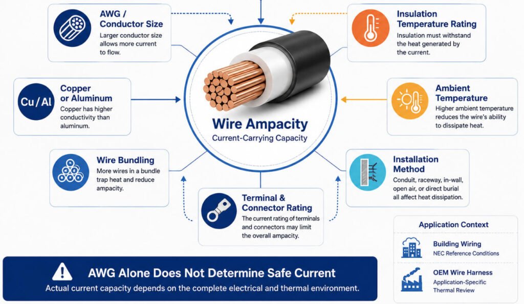
Wire ampacity is the maximum current a conductor can carry under specified conditions without exceeding its permitted operating temperature. However, AWG ampacity is not determined by wire gauge alone. The current carrying capacity of wire also depends on conductor material, insulation temperature rating, ambient temperature, bundling, installation method, and the current limits of terminals and connectors.
Standard NEC ampacity chart values apply to defined electrical installation conditions, while OEM wire harnesses require additional thermal and application-specific review.
This blog explains electrical wire ampacity with a complete AWG ampacity chart, 4 AWG ampacity, 60°C / 75°C / 90°C ratings, copper vs aluminum, temperature derating, bundling, voltage drop and terminal and connector limits that affect real wire current capacity.
What Is Wire Ampacity?
Wire ampacity is the maximum continuous current a conductor can carry under specified conditions without exceeding its allowable operating temperature. In practical terms, the ampacity meaning is not simply “how many amps a wire can handle,” because the permitted current depends on the conductor material, wire size, insulation temperature rating, ambient temperature, bundling, and installation conditions.
Conductor Size + Material + Temperature Rating + Installation Conditions → Allowable Ampacity
Ampacity should not be confused with actual circuit current, DC resistance, or connector current rating. A wire may have sufficient ampacity while the terminal, connector contact, or installation condition imposes a lower allowable current.
This is also why the same AWG size can appear with different wire current rating values in different tables or applications.
Ampacity vs Amperage
Ampacity vs amperage describes two different concepts. Amperage is the actual current flowing through a circuit, while ampacity is the maximum allowable current the conductor can carry under defined conditions.
For example, a circuit may normally draw 20 A, while the selected conductor has an allowable ampacity higher than 20 A after all required derating factors are considered.
Ampacity vs Wire Gauge
AWG tells you conductor size; it does not by itself determine the allowable current.
A larger conductor generally has lower resistance and can carry more current, but wire gauge ampacity still depends on conductor material, insulation rating, ambient temperature, bundling, installation method, and the applicable electrical or OEM specification.
For wire harness engineering, we therefore review AWG together with the complete thermal and electrical environment rather than assigning one universal ampacity value to every wire of the same gauge.
Complete AWG Wire Ampacity Chart
The following AWG ampacity chart provides reference current ratings for copper conductors at 60°C, 75°C, and 90°C temperature columns. These values are based on NEC Table 310.16 conditions for insulated conductors with not more than three current-carrying conductors in a raceway, cable, or earth, with a 30°C ambient temperature unless adjustment or correction factors are required.
| AWG Size | Area (mm²) | Copper 60°C | Copper 75°C | Copper 90°C |
|---|---|---|---|---|
| 14 AWG | 2.08 | 15 A | 20 A | 25 A |
| 12 AWG | 3.31 | 20 A | 25 A | 30 A |
| 10 AWG | 5.26 | 30 A | 35 A | 40 A |
| 8 AWG | 8.37 | 40 A | 50 A | 55 A |
| 6 AWG | 13.3 | 55 A | 65 A | 75 A |
| 4 AWG | 21.2 | 70 A | 85 A | 95 A |
| 3 AWG | 26.7 | 85 A | 100 A | 115 A |
| 2 AWG | 33.6 | 95 A | 115 A | 130 A |
| 1 AWG | 42.4 | 110 A | 130 A | 145 A |
| 1/0 AWG | 53.5 | 125 A | 150 A | 170 A |
| 2/0 AWG | 67.4 | 145 A | 175 A | 195 A |
| 3/0 AWG | 85 | 165 A | 200 A | 225 A |
| 4/0 AWG | 107.2 | 195 A | 230 A | 260 A |
The table is useful as a wire ampacity chart, wire gauge amp chart, and copper wire ampacity chart, but the listed values should not be treated as universal current limits for every cable or wire harness. NEC Table 310.16 applies to defined electrical installation conditions, and additional correction or adjustment may be required when ambient temperature changes or when more than three current-carrying conductors are grouped together.
For smaller conductors, applicable overcurrent-protection rules also need to be checked. For example, NEC requirements can limit 14 AWG, 12 AWG, and 10 AWG copper conductors to lower overcurrent-protection values even though higher-temperature columns in the table show higher ampacities.
In our harness engineering work, we use an ampacity chart as a reference point rather than the final wire-size decision. Installation temperature, bundle size, voltage drop, terminal and connector ratings, insulation type, and the applicable OEM specification still need to be reviewed.
This is especially important for automotive, EV, industrial, and equipment harnesses. A standard AWG current rating from an NEC table does not automatically become the allowable wire current capacity inside a tightly bundled harness, high-temperature enclosure, engine compartment, or application using connector contacts with a lower current rating.
What Is the Ampacity of 4 AWG Wire?
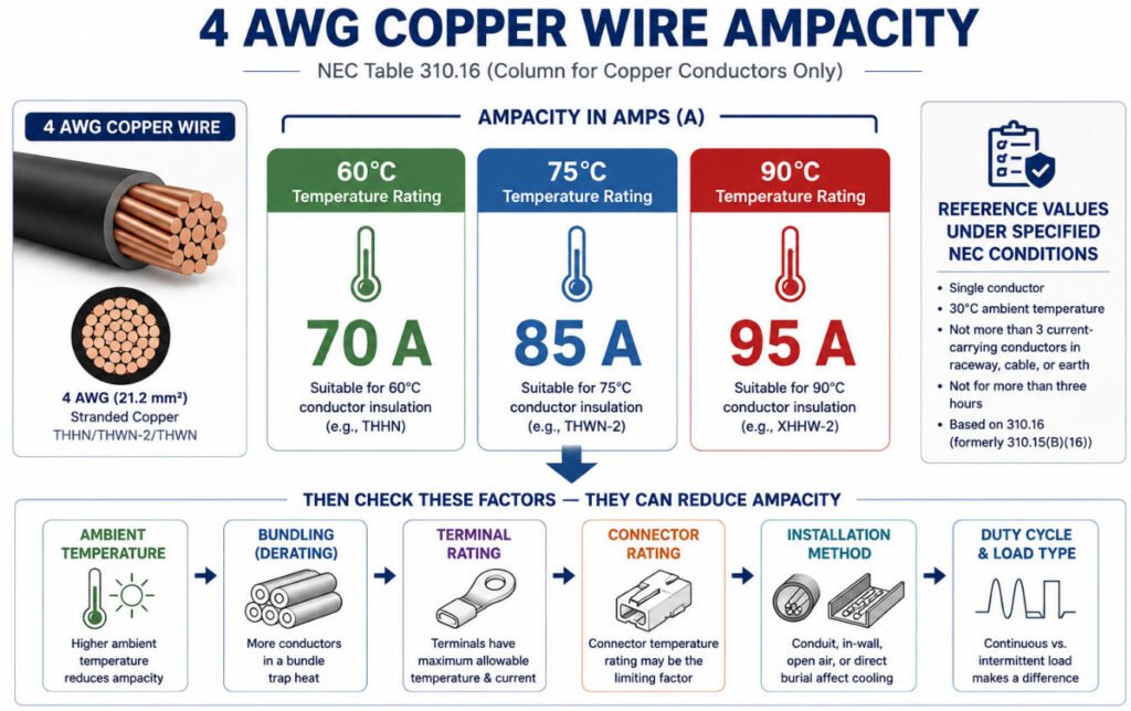
The 4 AWG wire ampacity for copper conductors is commonly referenced as 70 A at 60°C, 85 A at 75°C, and 95 A at 90°C under the specified conditions of NEC Table 310.16.
| 4 AWG Copper | Ampacity |
|---|---|
| 60°C | 70 A |
| 75°C | 85 A |
| 90°C | 95 A |
These values are reference ampacities under specified NEC conditions, not universal current limits for every 4 AWG cable or wire harness.
So, when someone asks how many amps can 4 AWG wire handle, the correct answer depends on more than conductor size.
Actual 4 AWG ampacity can be affected by:
- Insulation temperature rating
- Ambient temperature
- Number of wires in the bundle
- Installation method
- Terminal current rating
- Connector contact rating
- Cable routing and heat dissipation
- Continuous vs intermittent load
For example, a 4 AWG conductor installed in free air may have very different thermal behavior from the same conductor inside a tightly wrapped automotive harness near a heat source.
In harness engineering, we do not treat 4 gauge wire amps as one fixed value. Before approving a 4 AWG current rating, we also review the terminal, connector, bundle configuration, voltage drop, operating temperature, and applicable OEM specification.
A wire may meet the conductor ampacity requirement but still be limited by the connector or terminal system.
Common AWG Wire Ampacity Quick Reference
The following quick reference summarizes common copper wire sizes using NEC Table 310.16 ampacity values for the 60°C, 75°C, and 90°C columns. These values are useful starting points, but they are not universal current limits for every cable or wire harness application.
14 AWG Wire Ampacity
The 14 AWG ampacity is 15 A at 60°C, 20 A at 75°C, and 25 A at 90°C under the applicable NEC reference conditions. 14 AWG is commonly used in lower-current circuits, controls, lighting, and general wiring. Final selection should still consider terminal ratings, ambient temperature, bundling, voltage drop, and the applicable installation standard.
12 AWG Wire Ampacity
The 12 AWG ampacity is 20 A at 60°C, 25 A at 75°C, and 30 A at 90°C under specified NEC conditions. It is widely used for branch circuits, equipment wiring, and medium-current applications. For automotive or industrial harnesses, conductor temperature, bundle density, connector limits, and circuit length should also be reviewed.
10 AWG Wire Ampacity
The 10 AWG ampacity is 30 A at 60°C, 35 A at 75°C, and 40 A at 90°C under NEC reference conditions. 10 AWG is often considered for higher-current equipment, motors, power distribution, and battery-related circuits. Actual allowable current may be lower when installed in hot environments or dense wire bundles.
8 AWG Wire Ampacity
The 8 AWG ampacity is 40 A at 60°C, 50 A at 75°C, and 55 A at 90°C under specified NEC conditions. 8 AWG is commonly associated with higher-current power circuits and larger equipment loads. In wire harness design, voltage drop, terminal compatibility, conductor temperature, and routing conditions may determine whether a larger conductor is required.
6 AWG Wire Ampacity
The 6 AWG ampacity is 55 A at 60°C, 65 A at 75°C, and 75 A at 90°C under NEC reference conditions. It is commonly used where higher current capacity is required, including power distribution and battery connections. Connector contact ratings, crimp quality, bundle temperature, and continuous load requirements can become important limiting factors.
4 AWG Wire Ampacity
The 4 AWG ampacity is 70 A at 60°C, 85 A at 75°C, and 95 A at 90°C under specified NEC conditions. 4 AWG is often used for higher-current power, battery, charging, and industrial applications. These values should not be treated as universal limits for automotive or EV harnesses without reviewing thermal conditions, connectors, and duty cycle.
2 AWG Wire Ampacity
The 2 AWG ampacity is 95 A at 60°C, 115 A at 75°C, and 130 A at 90°C under NEC reference conditions. This conductor size is commonly found in high-current power distribution and battery systems. For OEM harnesses, terminal capacity, cable length, voltage drop, insulation system, and actual installation temperature must also be evaluated.
1 AWG Wire Ampacity
The 1 AWG wire ampacity is 110 A at 60°C, 130 A at 75°C, and 150 A at 90°C under specified NEC conditions. 1 AWG is generally used in higher-current feeders, battery connections, and industrial power circuits. Final current capability can still be limited by connectors, terminals, thermal environment, or application-specific standards.
1/0 AWG Wire Ampacity
The 1/0 AWG ampacity is 125 A at 60°C, 150 A at 75°C, and 170 A at 90°C under NEC reference conditions. 1/0 cable is often used in high-current power distribution, battery systems, and larger equipment. In vehicle or industrial harnesses, current capacity should be checked together with cable length, terminal design, heat exposure, and installation method.
2/0 AWG Wire Ampacity
The 2/0 AWG ampacity is 145 A at 60°C, 175 A at 75°C, and 195 A at 90°C under specified NEC conditions. This size is commonly used for heavy-duty power connections, large battery circuits, and high-current equipment. The finished system should also be checked for connector temperature rise, crimp resistance, routing, and voltage drop.
4/0 AWG Wire Ampacity
The 4/0 AWG ampacity is 195 A at 60°C, 230 A at 75°C, and 260 A at 90°C under NEC reference conditions. 4/0 conductors are typically used in very high-current power, battery, industrial, and heavy-equipment applications. Actual allowable current must still be verified against terminal ratings, installation temperature, bundling, cable construction, and the applicable engineering standard.
What Wire Size Do I Need for Different Amperage?
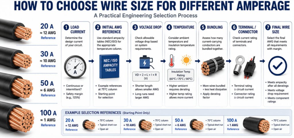
When selecting wire size for amps, the required conductor size depends on more than load current. A wire must satisfy ampacity, temperature, installation, voltage-drop, terminal, connector, and application-specific requirements.
The table below is a reference example using copper conductors and the 60°C ampacity column. It should not be treated as a universal wire size amperage chart for every electrical or wire harness application.
| Load Current | Typical Reference Wire Size | What Else to Check |
|---|---|---|
| 10 A | 14 AWG* | Length / voltage drop / application standard |
| 15 A | 14 AWG | Ambient temperature / terminals / installation |
| 20 A | 12 AWG | Voltage drop / bundling / connector rating |
| 30 A | 10 AWG | Continuous load / cable length / temperature |
| 40 A | 8 AWG | Bundling / terminal rating / voltage drop |
| 50 A | 6 AWG | Connector temperature rise / cable length |
| 60 A | 4 AWG | Terminals / bundling / installation temperature |
| 80 A | 3 AWG | Voltage drop / lug-crimp interface / thermal rise |
| 100 A | 1 AWG | Connection resistance / temperature rise / routing |
Note that: 14 AWG is shown because this quick-reference table starts at common NEC conductor sizes. Smaller wire may be appropriate in some equipment or OEM harness applications when permitted by the applicable standard and validated for the actual conditions.
For example
What Gauge Wire for 20 Amps?
For a 20 A load, 12 AWG copper is a common reference size under the 60°C column.
However, when choosing a wire gauge for amps in an OEM harness, also check cable length, ambient temperature, bundling, connector contact rating, and allowable voltage drop.
What Gauge Wire for 30 Amps?
For 30 A, 10 AWG copper is a common 60°C reference.
This does not mean every 30 A circuit should automatically use 10 AWG. A long 12 V or 24 V cable run, for example, may require a larger conductor because of voltage drop even when the ampacity requirement is satisfied.
What Gauge Wire for 40 Amps?
For 40 A, 8 AWG copper is a common reference size under the 60°C ampacity column.
In a tightly bundled wire harness or high-temperature environment, additional derating may be necessary. Terminal and connector ratings must also support the required continuous current.
What Gauge Wire for 50 Amps?
For 50 A, a conservative 60°C reference points to 6 AWG copper, which has a 55 A reference ampacity in that column.
Different permitted temperature columns and installation conditions may lead to a different result, so what gauge wire for 50 amps cannot be answered correctly without defining the complete application.
What Size Wire for 100 Amps?
Using the same 60°C copper reference, 1 AWG provides a 110 A reference ampacity.
For a 100 A OEM power harness, however, conductor size is only one part of the design. Lug or terminal resistance, crimp quality, cable length, voltage drop, connector temperature rise, ambient temperature, and continuous-duty conditions can all determine whether a larger conductor is required.
In our harness engineering work, we do not select wire by matching load current to a single wire size amperage chart.
A practical decision is closer to:
Load Current → Initial Wire Gauge → Temperature/Bundling Check → Voltage Drop Check → Terminal & Connector Check → Thermal Validation
This is especially important for automotive, EV, battery, and industrial power harnesses, where the correct wire size for amps may be larger than a basic ampacity table suggests.
What Factors Affect Wire Ampacity?
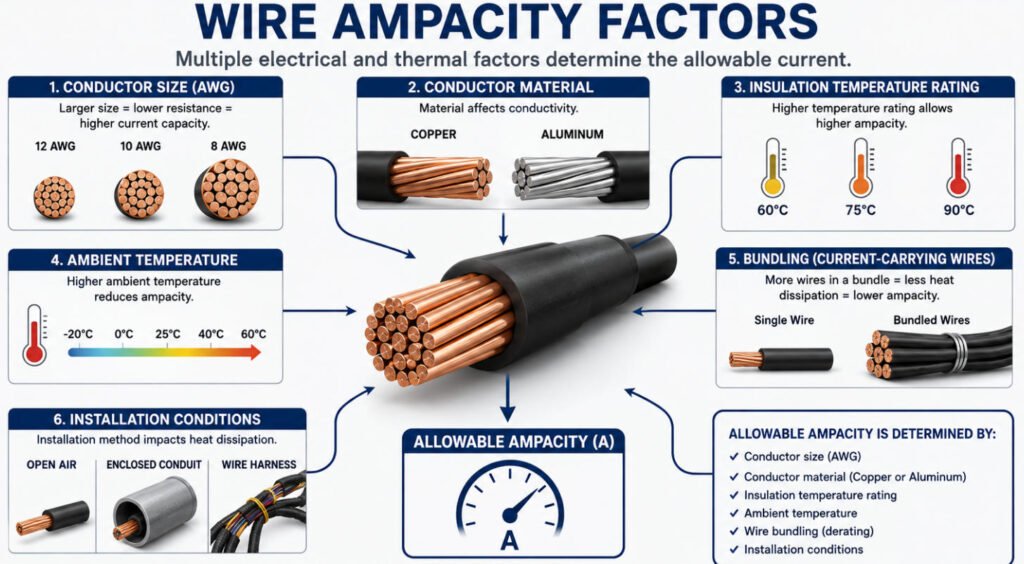
The wire current carrying capacity is determined by how much heat the conductor generates and how effectively that heat can dissipate without exceeding the permitted wire temperature rating. This is why the same AWG wire can have different allowable ampacity under different operating and installation conditions.
The main 6 factors affecting wire ampacity as follow:
| Factor | Effect on Ampacity | Engineering Concern |
|---|---|---|
| Conductor Size | Larger conductors generally carry more current | Resistance and heat generation |
| Copper vs Aluminum | Different electrical conductivity | Required conductor cross-section |
| Insulation Rating | Higher temperature-rated insulation may permit higher conductor temperature | Material temperature limit |
| Ambient Temperature | Higher ambient temperature reduces thermal margin | Temperature derating |
| Bundling | Multiple loaded wires trap heat | Bundle derating |
| Enclosure | Restricted airflow reduces heat dissipation | Temperature rise |
| Terminal / Connector | May become the current bottleneck | Contact resistance and heating |
| Duty Cycle | Changes average thermal loading | Continuous vs intermittent current |
1.Conductor Size and Material
Conductor cross-sectional area directly affects electrical resistance and heat generation. A larger conductor generally has lower resistance and therefore greater wire current carrying capacity.
Material also matters. Copper has higher electrical conductivity than aluminum, so an aluminum conductor generally requires a larger cross-sectional area to achieve comparable electrical performance. Material selection also affects weight, termination design, and connection reliability.
2.Insulation Temperature Rating
The insulation system establishes the maximum permitted conductor temperature under its applicable rating and conditions. Common ampacity references therefore provide different temperature columns, such as 60°C, 75°C, and 90°C.
However, a higher wire temperature rating does not automatically mean the complete circuit can operate at the corresponding higher ampacity. Terminals, connectors, equipment, and applicable standards may impose lower temperature or current limits.
3.Ambient Temperature
A conductor dissipates heat into its surroundings. When ambient temperature increases, less thermal margin remains between the environment and the maximum permitted conductor temperature.
For this reason, wire ampacity temperature conditions must be considered in hot environments such as engine compartments, industrial enclosures, battery systems, and equipment located near motors or other heat sources.
4.Number of Current-Carrying Conductors
When multiple loaded conductors are bundled together, each conductor generates heat while neighboring wires restrict heat dissipation.
A single wire in free air can therefore behave very differently from the same wire inside a densely packed harness. In our harness engineering reviews, bundle size and the number of simultaneously loaded circuits are important parameters when evaluating whether the selected AWG provides sufficient thermal margin.
5.Installation and Airflow
Routing conditions also affect cable current rating. A conductor installed in open air can generally dissipate heat more effectively than one routed through conduit, protective sleeving, a sealed enclosure, or a tightly packed harness.
Engineers should therefore evaluate the actual installation rather than applying a free-air or standard table value to every application.
6.Duty Cycle
Continuous and intermittent loads create different thermal conditions. A conductor carrying current continuously has less opportunity to cool, while an intermittent load may allow some heat to dissipate between operating cycles.
However, peak current should not automatically be treated as acceptable simply because it is intermittent. Current magnitude, ON/OFF time, conductor thermal characteristics, terminals, connectors, and application requirements must all be considered.
In our wire harness projects, we rarely approve a wire ampacity based on AWG alone. We review conductor material, insulation, ambient temperature, bundle conditions, routing, duty cycle, terminals, and connectors as part of the complete electrical and thermal system. In many OEM applications, the practical current limit is determined by the weakest thermal point not simply by the conductor itself.
How Does Temperature Derating Affect Wire Ampacity?
Wire ampacity values are normally based on defined reference conditions. When the actual ambient temperature is higher than the temperature assumed by the applicable standard or ampacity table, the allowable current may need to be reduced.
This process is called wire ampacity derating.
A wire that is acceptable at a moderate ambient temperature may not carry the same current safely in a 40°C, 50°C, or 80°C environment because less thermal margin is available for conductor heating.
The basic calculation is:
Base Ampacity × Temperature Correction Factor = Adjusted Ampacity
For example:
Base ampacity: 40 A
Temperature correction factor: 0.82
Adjusted ampacity: 32.8 A
In this example, the conductor should be evaluated using an adjusted ampacity of approximately 32.8 A rather than the original 40 A value.
The actual ampacity correction factor must come from the applicable standard, cable specification, or OEM design requirement. Correction factors vary with conductor temperature rating, ambient temperature, installation method, and the standard being used, so a generic wire derating chart should not be applied universally.
Why Higher Ambient Temperature Requires Derating
Electrical current generates heat inside the conductor. When the surrounding air is already hot, the wire cannot dissipate this heat as effectively.
In simplified form:
Higher Ambient Temperature → Lower Thermal Margin → Lower Allowable Current
This is why temperature derating wire calculations become increasingly important as ambient temperature rises.
A 90°C-rated wire operating in a 25°C environment has significantly more thermal margin than the same wire operating near an 80°C heat source. However, the usable current still depends on the applicable temperature correction factor and other installation conditions.
Factory Perspective
High temperature operating conditions are common in real wire harness applications.
Typical examples include:
- Automotive engine bays
- Areas near motors or generators
- Battery and power distribution systems
- Industrial equipment enclosures
- Control cabinets with limited ventilation
- Harnesses routed close to heaters, exhaust systems, or other heat sources
For these applications, Yihetai recommends defining the maximum expected ambient temperature during the design stage and applying the appropriate temperature correction factor before finalizing the wire size.
Temperature derating should also be evaluated together with bundling, airflow, terminal ratings, connector current limits, and actual duty cycle rather than treating ambient temperature as an isolated factor.
How Does Wire Bundling Affect Ampacity?
How Does Wire Bundling Affect Ampacity?
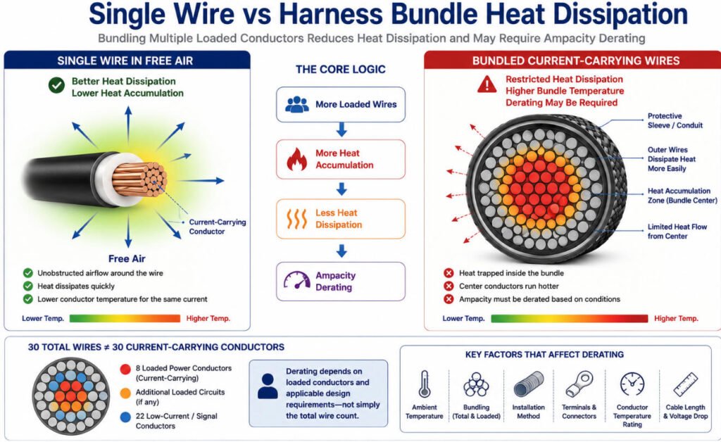
Wire bundling can significantly affect ampacity because multiple loaded conductors generate heat in the same confined area.
A single wire installed in free air can dissipate heat relatively easily. When many current-carrying wires are grouped into a harness, sleeve, conduit, or enclosed routing path, heat can accumulate inside the bundle and reduce the allowable current for each conductor.
In simplified form:
More Loaded Wires → More Heat Accumulation → Less Heat Dissipation → Derating Required
This is why wire bundle derating and cable bundle derating are important when determining real wire harness ampacity.
Why Harness Bundles Run Hotter
Every current-carrying conductor generates resistive heat.
When wires are installed individually, a larger portion of the conductor surface is exposed to surrounding air. Inside a dense harness bundle, however, many conductors are surrounded by other warm wires rather than cooler air.
Heat generated near the center of the bundle can therefore dissipate more slowly than heat from conductors located near the outside.
The thermal condition can become more severe when the harness is additionally covered with:
- PVC tape
- Braided sleeving
- Corrugated conduit
- Heat-shrink tubing
- Protective jackets
- Foam or insulation
- Sealed enclosure systems
For this reason, the ampacity of a conductor inside a large harness should not automatically be assumed to be the same as the rating of the same wire installed alone.
Current-Carrying Conductors vs Total Wires
For current carrying conductor derating, the number of electrically loaded conductors is often more important than simply counting every wire in the harness.
A harness may contain 30 wires, but not all 30 necessarily carry significant current at the same time.
Engineers should therefore consider:
- How many conductors carry current simultaneously
- Continuous current in each circuit
- Peak current and duty cycle
- Power circuits versus low-current signal circuits
- Return conductors where applicable
- Simultaneous operating conditions
For example, a bundle containing several high-current motor, heater, or power supply circuits can create a much greater thermal load than a similarly sized bundle consisting mainly of sensor and communication wires.
The applicable ampacity derating method should always follow the relevant standard, cable specification, or OEM design requirement.
Bundle Diameter and Installation
Bundle geometry also affects heat dissipation.
As the bundle diameter increases, conductors near the center are located farther from the surrounding air and may experience higher operating temperatures.
Important design factors include:
Bundle Diameter + Number of Loaded Conductors + Covering Material + Airflow + Ambient Temperature
Installation location also matters.
A harness routed openly through a ventilated area may cool more effectively than the same bundle installed:
- Inside conduit
- Behind interior panels
- Inside a sealed electrical enclosure
- Near an engine or motor
- Beside other heat-generating components
- Under thick protective wrapping
This is why wire bundle derating should be evaluated together with ambient temperature and the actual installation environment rather than as a standalone correction.
In our factory and engineering reviews, we often see designs where the selected AWG appears sufficient individually but becomes questionable after multiple loaded circuits are bundled together inside sleeving, conduit, or a sealed enclosure.
For custom wire harness projects, Yihetai recommends reviewing the number of simultaneously loaded conductors, expected current, bundle diameter, covering materials, ambient temperature, routing, and connector limitations before finalizing the wire size.
A wire that meets the required current rating individually may still require ampacity derating when incorporated into the finished harness.
Ampacity vs Voltage Drop: Which Determines Wire Size?
Ampacity vs Voltage Drop: Which Determines Wire Size?
Ampacity vs voltage drop are two different limits that must both be checked when selecting wire size.
Ampacity is mainly a thermal limitation. It determines whether the conductor can carry the required current without exceeding its permitted temperature.
Voltage drop is an electrical performance limitation. It determines how much voltage is lost in the wire before power reaches the load.
A wire may therefore pass the ampacity check but still be too small because of excessive wire voltage drop.
The basic relationship is:
Voltage Drop = Current × Circuit Resistance
Since conductor resistance increases with cable length, longer runs usually require a larger conductor to keep voltage drop within an acceptable limit.
Why Voltage Drop Matters in DC Systems
Voltage drop is especially important in:
- 12V automotive systems
- 24V industrial equipment
- 48V systems
- Long cable runs
- Motors and actuators
- Battery systems
- Pumps, heaters, and solenoids
Low-voltage systems are particularly sensitive because the same absolute voltage loss represents a larger percentage of the supply voltage.
For example, a 1 V drop in a 12 V system is much more significant than a 1 V drop in a higher-voltage system.
Example: Ampacity Passes, Voltage Drop Fails
Assume a 12 V motor requires:
- Load current: 20 A
- One-way cable length: 5 m
- Copper conductor
- 12 AWG wire
A 12 AWG conductor may appear acceptable from an ampacity standpoint under certain reference conditions. However, because current must travel through both the supply and return path, the total circuit length is approximately 10 m.
Using an approximate copper resistance of 5.2 mΩ/m for 12 AWG:
Circuit Resistance ≈ 0.052 Ω
Then:
Voltage Drop = 20 A × 0.052 Ω ≈ 1.04 V
That is approximately:
1.04 ÷ 12 × 100 ≈ 8.7% voltage drop
For many motor or electronic loads, that may be too high. The engineer may therefore select the next larger AWG even though 12 AWG passed the basic ampacity check.
Wire Gauge, Amps, and Distance Must Be Checked Together
This is why a voltage drop wire size calculation should include:
- Load current
- Supply voltage
- One-way cable length
- Supply and return path
- Conductor resistance
- Allowable voltage drop
- Operating temperature
- Terminal and connector resistance
A practical selection process is:
Ampacity Check → Voltage Drop Check → Terminal/Connector Check → Final Wire Size
For long DC circuits, wire gauge amps distance can be more important than the basic ampacity table.
Manufacturer Note
In automotive, battery, motor, and industrial harness projects, we often see circuits where the initial AWG is thermally acceptable but the wire size by distance calculation requires a larger conductor.
This is especially common in 12V and 24V systems, where voltage loss can cause slow motors, weak actuators, reduced heater output, unstable electronics, or poor charging performance.
For this reason, a 12V wire size chart or generic DC wire size table should be used only as a starting point. Final conductor size should satisfy both ampacity and voltage-drop requirements under the actual installation conditions.
How Is Automotive Wire Ampacity Different?
Automotive wire ampacity is not determined the same way as building-wire ampacity. NEC ampacity tables apply to defined electrical installation conditions and should not be treated as universal current ratings for vehicle wiring.
In automotive applications, allowable current depends on the complete installation environment, including:
- 12V, 24V, or 48V system voltage
- Engine-compartment temperature
- Compact harness bundles
- Thin-wall automotive wire
- Vibration and mechanical movement
- Connector contact limits
- Voltage drop
- Continuous vs intermittent load
- OEM-specific requirements
This is why an automotive wire ampacity chart should be used only as a reference unless the actual vehicle conditions and applicable cable standard are known.
SAE and ISO Automotive Wire
Automotive cable standards focus on cable construction, materials, dimensions, temperature capability, and performance requirements rather than assigning one universal current value to every AWG size.
For example, the current SAE J1128 standard covers low-voltage primary cable for surface-vehicle electrical systems at nominal voltages of 60 VDC or less.
ISO 6722 is also widely associated with road-vehicle low-voltage cable requirements. In practice, however, engineers should not interpret standards such as SAE J1128 or ISO 6722 as saying that “a certain AWG always equals a certain number of amps.”
Actual SAE wire ampacity or vehicle current capability still depends on:
- Wire construction
- Insulation class
- Ambient temperature
- Bundle loading
- Cable length
- Terminal system
- Connector cavity loading
- Duty cycle
- OEM validation criteria
Engine-Bay vs Cabin Harness
The same wire size can behave very differently depending on where it is installed in the vehicle.
An engine-bay harness may be exposed to:
- Higher ambient temperature
- Radiant heat from engine or exhaust components
- Oil and chemical exposure
- Vibration
- Tight routing
- Dense bundle sections
A cabin harness generally operates in a cooler environment, but may still have compact routing, multiple loaded circuits, connector-density limits, and voltage-drop concerns.
So the same vehicle wire size may have more thermal margin in the cabin than near a high-temperature powertrain area.
Manufacturer Note
In automotive harness engineering, we do not approve wire size from a generic automotive wire size chart alone.
A practical review includes:
Current Load + Wire Size + Temperature Class + Bundle Condition + Cable Length + Voltage Drop + Terminal Rating + Connector Loading + OEM Specification
This is especially important in modern vehicles where compact harnesses, higher electrical loads, and 48V architectures can increase thermal and packaging pressure. The final automotive wire current rating should therefore be validated for the actual vehicle installation rather than copied from a building-wire ampacity table.
Copper vs Aluminum vs Tinned Copper Wire Ampacity
Conductor material affects electrical resistance, required cross-sectional area, weight, corrosion resistance, and termination design. Therefore, comparing copper wire ampacity and aluminum wire ampacity involves more than asking which conductor can carry more current.
For the same conductor size and comparable conditions, copper generally has lower electrical resistance than aluminum. Tinned copper retains the basic electrical characteristics of copper while adding a protective tin coating that improves corrosion resistance in demanding environments.
The table below compares the key electrical, mechanical, and termination characteristics of bare copper, tinned copper, and aluminum conductors.
| Conductor | Conductivity | Weight | Termination Considerations | Typical Applications |
|---|---|---|---|---|
| Bare Copper | High | Higher than aluminum | Widely compatible with standard crimp terminals and connectors | Automotive, industrial equipment, appliances, general wire harnesses |
| Tinned Copper | High, with slightly different resistance depending on construction | Similar to bare copper | Terminal and crimp system must match conductor construction | Marine, automotive, industrial, outdoor and corrosive environments |
| Aluminum | Lower than copper | Significantly lighter | Requires compatible terminals, controlled crimping, and attention to oxide formation | Weight-sensitive power distribution and selected automotive or industrial applications |
Can the Connector or Terminal Limit Wire Ampacity?
Yes. In a wire harness, the allowable current is determined by the complete electrical connection system, not by wire AWG alone.
Wire → Crimp → Terminal → Connector → PCB / Device
Each interface adds electrical resistance and generates heat, so the lowest-rated or highest-resistance point can become the limiting factor for the overall wire harness current rating.
Terminal Current Rating
A terminal has its own terminal current rating, which depends on factors such as terminal size, material, plating, contact geometry, conductor range, and permitted temperature rise. A wire may have adequate ampacity while the terminal becomes the thermal limit.
Connector Contact Rating
The connector current rating depends on the contact system, number of loaded cavities, housing material, ambient temperature, and mating conditions. Multiple high-current contacts inside one connector can also increase local temperature.
Crimp Resistance
A correctly made crimp should create a low-resistance electrical and mechanical connection. Key production parameters include:
- Crimp height
- Conductor compression
- Conductor brush position
- Terminal material
- Plating
- Contact resistance
- Temperature rise
Incorrect crimp height, damaged strands, insufficient compression, or poor conductor positioning can increase crimp resistance and create a localized hot spot.
For this reason, terminal ampacity and connector ampacity should be reviewed together with conductor ampacity when determining the final circuit current capability.
How Do You Calculate the Required Wire Size?
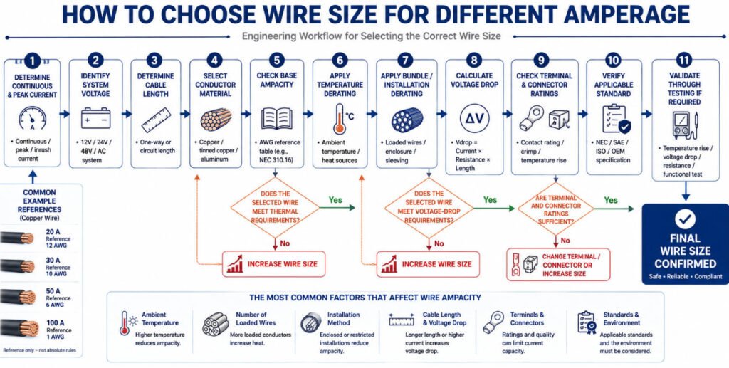
To determine the correct conductor size, engineers should evaluate electrical load, thermal conditions, voltage drop, installation constraints, and connection-system limits together. A practical wire size calculation should be process follow 11 steps:
Step 1: Determine Continuous and Peak Current
Identify both normal operating current and any short-duration peak or inrush current.
Step 2: Identify System Voltage
Confirm whether the circuit operates at 12V, 24V, 48V, mains voltage, or another system voltage.
Step 3: Determine Cable Length
Longer circuits have more resistance and greater voltage drop, which may require a larger conductor.
Step 4: Select Conductor Material
Choose copper, tinned copper, aluminum, or another specified conductor material.
Step 5: Check Base Ampacity
Use the applicable AWG selection or conductor ampacity reference as the starting point.
Step 6: Apply Temperature Derating
Adjust the allowable current for elevated ambient temperature and conductor temperature limits.
Step 7: Apply Bundle / Installation Derating
Consider wire bundling, sleeving, conduit, enclosure, airflow, and the number of simultaneously loaded circuits.
Step 8: Calculate Voltage Drop
Verify that the selected wire delivers sufficient voltage to the load over the required cable length.
Step 9: Check Terminal and Connector Ratings
Confirm that terminals, crimps, contacts, and connectors can carry the required current without excessive temperature rise.
Step 10: Verify the Applicable Standard
Check the relevant electrical code, automotive standard, product specification, or OEM requirement.
Step 11: Validate Through Testing if Required
For critical or high-current applications, temperature-rise, voltage-drop, contact-resistance, or current-load testing may be required.
The final wire gauge calculation should therefore satisfy all design constraints:
Final Wire Size = Size That Meets Thermal + Voltage Drop + Mechanical + Connector + Applicable-Standard Requirements.
How to Specify Wire Size for a Custom Wire Harness
When requesting a custom wire harness, providing the actual electrical and environmental requirements helps the manufacturer review wire size more accurately.
For an OEM wire harness or custom cable assembly, we recommend including the following information:
| Parameter | Example |
|---|---|
| System Voltage | 12V / 24V / 48V |
| Continuous Current | XX A |
| Peak Current | XX A |
| Wire Length | XX mm |
| Wire Gauge | AWG / mm² if known |
| Wire Type | UL / SAE / ISO / custom |
| Temperature | XX°C |
| Connector | TE / Molex / JST / etc. |
| Environment | Vibration / moisture / heat |
| Bundle Condition | Single / bundled |
| Voltage Drop Limit | If specified |
| Applicable Standard | OEM / SAE / UL / etc. |
If the wire size has not yet been finalized, these parameters give our engineers a better basis for reviewing the conductor, terminal, connector, and manufacturing requirements together.
For example, a preliminary wire harness design may appear acceptable based on ampacity alone, but cable length, bundle temperature, connector contact rating, or voltage-drop limits may require a larger conductor or a different terminal system.
As a wire harness manufacturer and OEM cable assembly manufacturer, Yihetai can review customer drawings, BOMs, connector part numbers, current requirements, and samples before production. This helps confirm that the selected wire size is practical for both electrical performance and manufacturing.
Conclusion
Wire gauge alone does not determine safe current capacity. The correct conductor size must be selected by evaluating ampacity + temperature + bundling + voltage drop + terminal + connector + environment + applicable standard as one complete system.
For OEM projects, this system-level review is especially important because a wire that looks acceptable on an ampacity chart may still fail voltage-drop, thermal, connector, or installation requirements.
If you are developing a custom wire harness, you can send Yihetai your drawing, BOM, wire specification, terminal or connector part numbers, current, voltage, cable length, application environment, or sample for manufacturability and engineering review.
Related Wire Harness Articles:
- Wire Gauge Guide: AWG Sizes, Diameter, Amperage & How to Choose the Right Wire
- Why Terminal Selection Important in Custom Wire Harnesses?
- Types of Wiring Harnesses in a Car: Complete Guide to Automotive and EV Wiring Harnesses
- Automotive Wire Harness Protection Materials: Corrugated Tube, Tape, Sleeves and Foam Compared
- How to Choose the Right Power Cable Type for Your Project?