
Jumper wires are the little bridge cables I reach for when I’m prototyping. They make quick interconnects easy, letting me link a breadboard, sensor, or dev board in seconds so I can prove an idea fast. But I’ve also learned the hard way that a simple jumper can derail an entire build. You plug it in and it doesn’t fit, or it fits but feels loose. Suddenly your LED flickers, your sensor readings jump around, or your circuit works perfectly until you touch the board and it fails again. That kind of noise and intermittent fault is frustrating because it steals the most valuable time I have, debugging time.
That’s why I’m writing this blog. I’ll show you how I choose male, female, or mixed end jumper wires based on real design needs. I’ll break it down by what you’re connecting to, how stable the connection must be, and what to do when signals get sensitive. By the end, you’ll pick the right jumper the first time.
What Is a Jumper Wire?
A jumper wire is a short, flexible, insulated wire with a connector or pin on one or both ends. I use jumper wires to make fast, temporary connections between components without soldering, especially when I’m testing ideas or debugging a circuit.
In electronic design, jumper wires are most common during prototyping. They let me quickly route signals or power between boards, modules, and sensors so I can validate a design before committing to a PCB layout or a production cable.
You’ll see jumper wires used all the time on popular platforms like:
- Breadboards for quick circuit builds
- Arduino projects (connecting sensors, displays, modules)
- Raspberry Pi GPIO wiring
- Other development boards, breakout modules, and sensor boards
Understanding Connector “Gender” in Electronics
When I say “connector gender” in electronics, I’m using a simple shortcut that helps me avoid the most common jumper-wire mistake: buying the right wire length and pitch, but the wrong end type. Once I train myself to look at the connection point and ask “Do I see pins or do I see holes?”, choosing the correct jumper wire becomes quick and reliable. This is especially important in prototyping, where one loose or mismatched connection can look like a software bug, a bad sensor, or a noisy power issue.
What is a male connector (pin)?
A male connector is the end with a metal pin sticking out.
- Looks like: a visible pin or blade that protrudes
- What it does: it inserts into a matching socket or hole
- Where I see it often: header pins on modules, GPIO pin rows, some PCB headers, and many male-ended jumper wires
In my head, I think of the male end as the “plug” side.
What is a female connector (socket)?
A female connector is the end with a socket (receptacle) that receives a pin.
- Looks like: a housing with a hole; the metal contact is inside
- What it does: it slides onto or accepts a male pin
- Where I see it often: Arduino-style female headers, pre-crimp Dupont housings, cable assemblies designed to mate with pins
In my head, I think of the female end as the “receiver” side.
How male and female connectors fit together (visual/mental picture)
The simplest mental model I use is:
Pin goes into socket.
If I can see a pin, I need a socket to mate with it. If I can see holes, I need a pin to insert.
Here’s a simple picture you can imagine:
- A male pin is like a small metal post.
- A female socket is like a small opening that grips that post.
Why matching gender to header type is critical for compatibility
This is critical because gender determines whether the connection is physically possible and whether it will be stable.
- If my board has male header pins (pins sticking up), I must use a female jumper end to connect.
- If my board has female header sockets (holes), I must use a male jumper end to connect.
- If I pick the wrong gender, it simply won’t fit, or it will fit poorly and create loose contact, which can cause flicker, noise, or intermittent faults.
The rule I follow every time:
- Pins visible = choose female
- Holes visible = choose male
And when I’m connecting two different interfaces (for example a breadboard to a module), I often end up using male-to-female jumpers because one side needs a pin and the other side needs a socket.

What Are TheTypes of Jumper Wires?
Once I understand connector “gender” on my boards and modules, the next logical step is to match them with the right type of jumper wire. In practice, I’m really just choosing between three basic combinations: male-to-male, female-to-female, and male-to-female. Each one solves a slightly different connection problem, and knowing the strengths and weaknesses of each type saves me a lot of frustration when I’m wiring up a prototype.
What Are the Types of Jumper Wires?
1.Male-to-Male (M–M) Jumper Wires
Description
A male-to-male jumper wire has exposed metal pins on both ends. Each side is a male connector, ready to plug into a female socket or breadboard hole.
Typical use cases
In my projects, I reach for M–M jumpers when I need to connect:
- Breadboard to breadboard
- Linking two breadboards together
- Jumping signals across different sections of the same breadboard
Pros
- Ideal for breadboard-based prototyping
- Simple and intuitive: pin into hole, done
- Very common and available in mixed color and length kits
Cons
- Useless if both sides of my connection are male headers (pin-to-pin)
- Not suitable for directly connecting to bare component leads without some workaround
2.Female-to-Female (F–F) Jumper Wires
Description
A female-to-female jumper wire has a socket on both ends. Each side is a female connector designed to receive a male pin.
Typical use cases
I grab F–F jumpers when I need to:
- Connect boards with male headers
- Linking two PCBs that both expose male pin headers
- Bridging between a Raspberry Pi’s GPIO header and another board with male pins
- Link two modules together
- Sensor module (male pins) to communication module (male pins)
- Debug adapters, small custom boards, or shields that all use male headers
Pros
- Perfect whenever I have male pins on both sides
- Cleaner, more secure than trying to use loose wires or clips
- Great for making quick “board-to-board” harnesses during development
Cons
- Can’t plug directly into a breadboard, since that also acts like a female connector
- Not helpful if one side of the connection is already a female header
3.Male-to-Female (M–F) Jumper Wires
Description
A male-to-female jumper wire has a male pin on one end and a female socket on the other. One side plugs in the other side receives a pin.
Why they’re considered the most versatile
In my toolbox, M–F jumpers are the “Swiss army knife” of jumper wires. With one end male and one end female, they can bridge almost any combination of header types, act as adapters, and extend other jumper wires.
Typical use cases
- Extending existing jumper wires
- Male end plugs into a female jumper; female end receives a male pin
- Quickly lengthen a connection without replacing cables entirely
- Adapting between different header types
- Breadboard (female) ↔ module with male pins
- Arduino female headers ↔ another board’s male header
- Converting a F–F connection into effectively M–F or M–M when combined
Pros
- Extremely flexible and adaptable in mixed setups
- Lets me solve “male-to-male” or “female-to-female” problems by acting as an adapter
- Reduces the number of different jumper kits I need to keep on hand
Cons
- Slightly more complex to manage in large bundles (mixed ends can tangle or be confusing)
- If I rely on them for everything, my wiring can become messy without planning
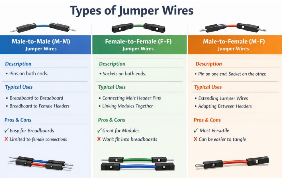
Suggested Image for This Section
To go with this explanation, I’d create one clear comparison graphic:
Top row
- M–M jumper labeled “Male-to-Male” with visible pins on both ends
- F–F jumper labeled “Female-to-Female” with sockets on both ends
- M–F jumper labeled “Male-to-Female” with one pin and one socket
Bottom row
Simple icons showing each type in use:
- M–M between breadboard and Arduino female header
- F–F between two PCBs with male headers
With this visual in mind, it becomes much easier for me and my readers to pick the right jumper type at a glance.
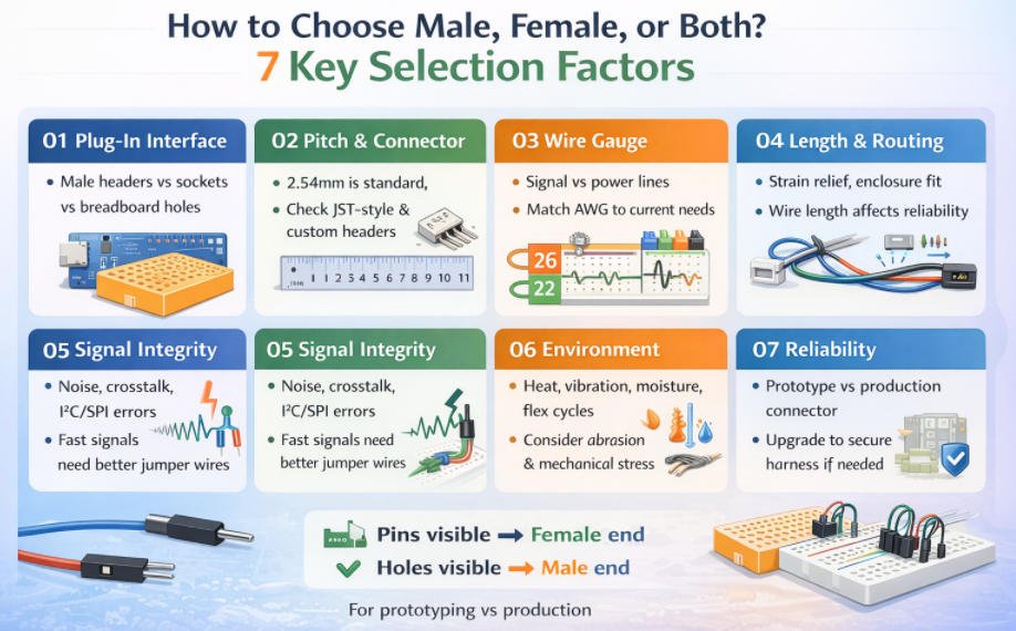
How to Choose Male, Female, or Both? 7 Keys Selection Factors
When I’m choosing between male, female, or mixed-end jumper wires, I don’t start by guessing the “right” type. I start by looking at the real-world connection points and asking what will physically mate, what will carry the current safely, and what will stay reliable once the project moves beyond a quick bench test. Below are the key selection factors I use to choose correctly the first time.
1.What are you plugging into?
This is the fastest way to decide the end type.
- Breadboard holes are essentially female, so I usually need male pins to plug in.
- Male pin headers (pins sticking up) require a female socket jumper end.
- Female sockets/headers (holes on the board) require a male pin jumper end.
My simple rule:
- If I see pins, I choose female.
- If I see holes, I choose male
2.Pitch and connector compatibility
Even if the gender is right, the jumper can still fail if the pitch is wrong.
- 2.54 mm (0.1”) is the most common for breadboards and many dev boards.
- JST-style connectors (often used on batteries and small modules) typically use different pitches and housings, so standard Dupont jumpers won’t directly mate.
- Some boards use custom headers or smaller pitches, so I confirm pitch before ordering.
If I’m unsure, I measure the header pitch or check the module datasheet. This one check prevents most “doesn’t fit” issues.
3.Wire gauge (AWG) and current needs
I pick gauge based on whether the wire is carrying signal or power.
- Signals (GPIO, I2C, UART, logic lines) usually work with thinner wire.
- Power lines (motors, heaters, LED strips, relays) need thicker gauge and better crimps to avoid voltage drop and heat.
If I feel the wire getting warm, see brownouts, or notice dimming/flicker under load, I treat it as a gauge and connection-quality warning sign.
4.Cable length and routing
Length is not just convenience. It affects reliability.
- I keep wires as short as practical to reduce clutter, resistance, and accidental snags.
- I plan routing around enclosure space, bends, and moving parts.
- If something moves or gets tugged, I add strain relief (tie-down points, clips, or a simple loop) so the crimp isn’t taking the force.
Long jumpers also act like little antennas, which leads directly to the next factor.
5.Signal integrity (noise, crosstalk, and fast edges)
When signals get sensitive, jumper choice matters more than people expect.
I pay extra attention when I’m using:
- PWM lines (motors, dimming)
- Encoders
- I2C and SPI (especially at higher speeds)
What I do in practice:
- Keep I2C/SPI wires short and avoid running them parallel to high-current wires.
- Use ground nearby (a return path close to the signal) to reduce noise.
- Separate “noisy” lines (PWM, motor power) from “quiet” sensor lines.
If noise persists, I move from loose jumpers to a more controlled cable or shielding strategy.
If I see random resets, jittery readings, or flaky communication, I suspect wiring before I blame firmware.
6.Environment (heat, vibration, moisture, abrasion, flex cycles)
Prototypes live on desks. Real products live in the real world.
- Vibration can loosen friction-fit jumpers and cause intermittent faults.
- Heat can soften plastics or degrade insulation.
- Moisture and dust can corrode contacts.
Abrasion and repeated bending can break conductors at the crimp or at stress points.
If the design will move, vibrate, or flex, I stop trusting loose jumpers and plan a retention connector or harness.
7.Reliability requirements (prototype convenience vs production-grade retention)
This is where I decide whether jumpers are still appropriate.
- For fast experiments, jumpers are perfect because they’re quick and flexible.
- For anything I ship, demo repeatedly, or mount in an enclosure, I prefer production-grade retention, consistent crimps, and proper testing.
My mindset is: jumpers help me learn fast, but they’re rarely the final answer. Once the design stabilizes, I plan the interconnect the way I plan the PCB: deliberately.
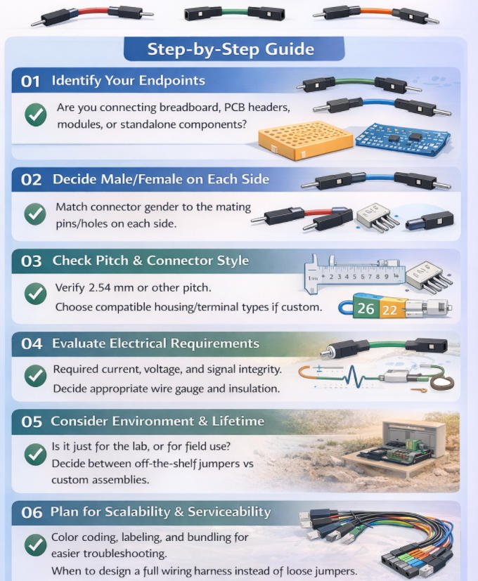
Step-by-Step: How to Choose the Right Jumper Wire for Your Design
By this point I have already thought about male or female connectors and the different jumper types. When I sit down with a real project though, I like to follow a clear checklist. That way I am not guessing which jumper wire might work. I move through each step and let the answers point me to the right choice.
Step by step: How I choose the right jumper wire
1.Identify my end points
First I look carefully at what I am connecting on each side.
I ask myself
- Is this a breadboard, which behaves like a field of small sockets
- Is it a PCB header with exposed pins
- Is it a module, sensor or other board with its own connector
- Is it a loose part such as a switch, LED or motor lead
Once I know the exact end points, the rest of the decisions become much easier.
2.Decide male or female on each side
Next I match connector gender.
Breadboard holes act like female sockets, so they expect a male jumper end.
Male pin headers on a PCB or module expect a female jumper end.
Female headers or sockets on a board expect a male jumper end.
From there the jumper type is obvious.
Male to female needs an M to F jumper.
Female to female needs an M to M jumper.
Male to male needs an F to F jumper.
If I respect this rule, most fit problems and loose connections disappear.
3.Check pitch and connector style
Then I confirm the mechanical details.
I check whether the header uses the common 2.54 millimeter pitch or something different.
If I see JST style connectors, automotive plugs or any custom housing, I know that plain jumper housings might not fit securely or lock in place.
For these non standard connectors I still decide male or female according to the mating side, but I plan to use proper crimps and housings or a custom cable assembly instead of bare jumpers.
4.Evaluate electrical requirements
Now I consider what flows through the wire.
How much current and voltage does this connection carry
Is it a low level digital signal such as I2C, SPI or GPIO
Is it a power feed for motors, heaters or light strips
Based on those answers I choose a suitable wire gauge, contact quality and insulation rating.
Thin jumper wire is fine for logic signals on the bench.
For higher current I move to thicker conductors and more robust contacts, even if I still use the same male or female arrangement.
5.Consider environment and lifetime
Then I think about where and how the wiring will be used.
On a clean lab bench, generic jumpers are usually good enough.
Inside a machine or enclosure with vibration or temperature changes, loose friction fit pins can work themselves free.
In outdoor or dirty environments, or near moving parts, I avoid exposed jumpers and plan for sealed or locking connectors with strain relief.
This is where I decide whether my jumper choice is temporary for development or must survive in real service.
6.Plan for scalability and serviceability
Finally I ask how this wiring will be maintained in the future.
Will someone else need to understand and debug it
Do I need clear color coding, labels and bundling so the layout is readable
If the design is heading toward production, I stop relying on loose jumpers and design a proper wiring harness.
That means correct lengths, grouped cables, labeled connectors and complete testing.
Male and female jumper wires remain extremely useful, but mainly as tools for prototyping and validation before I freeze the final interconnect for a production ready product.
Practical “Pick This If…” Scenarios
By this point, I’ve thought about gender, pitch, current, and environmentbut when I’m actually at the bench, I don’t want theory, I want quick decisions. In practice, I fall back on a few simple “pick this if…” patterns that cover 90% of my real projects.
Breadboard prototyping → usually Male-to-Male
When I’m working purely on a breadboard, I almost always grab male-to-male (M–M) jumpers.
- Breadboards are designed for male pins, so M–M lets me hop signals from one row to another or from one breadboard to a second board.
- Power rails, ground buses, and quick logic links are all easy with M–M.
If both endpoints are breadboards or female headers, M–M is my default.
Sensor/module with male pins → controller board → often Female-to-Female 小一号
If my sensor or module exposes male header pins and my controller board also has male pins, I reach for female-to-female (F–F) jumpers.
- Each female socket slips over a row of male pins.
- This is common with breakout boards and some custom PCBs.
Any time I see pins on both sides, F–F is usually the cleanest solution.
Arduino-style dev board + sensor module + breadboard mix → Male-to-Female 小
In a mixed setup—Arduino-style dev board, sensor module, and breadboard—I find male-to-female (M–F) jumpers the most flexible.
- The male end can plug into the breadboard or a female header.
- The female end can plug onto a male pin header on a module or shield.
- When I’m mixing platforms and need “adapter-like” behavior, M–F gives me maximum freedom without a pile of different cables.
Enclosure build with repeated plugging/unplugging → Locking connectors or custom cable
If I know a connection will be plugged and unplugged often inside an enclosure (for maintenance, swapping modules, etc.), I move beyond loose dupont jumpers.
- I prefer locking connectors (like JST, latch housings, or keyed headers).
- I’ll often design a custom cable assembly with proper strain relief.
Here, the focus isn’t just male vs female—it’s retention, durability, and ease of service.
Vibration or motion (robotics/industrial) → Secured connectors / harness, not loose jumpers 小
For robots, moving machinery, or industrial panels, I avoid relying on loose dupont jumpers entirely.
- Vibration can slowly walk jumpers out of their sockets, causing intermittent faults.
- Instead, I use crimped connectors, locking housings, and proper wire harnesses tied down to the chassis.
In these cases, jumper wires are fine for early tests, but the final design should use a secured connector system that won’t shake loose the first time the motor spins.
When It’s Time to Move Beyond Jumpers: Custom Wire Harness Solutions
If your products still rely on loose jumper wires and ad-hoc cabling, there’s a point where “good enough” quietly becomes a risk. As systems get more complex and volumes increase, simple jumpers start to cost you time, money, and reputation.
That’s exactly where custom wire harnesses from Yihetai step in bringing order, reliability, and scalability to your wiring.
1.Signs You’ve Outgrown Off-the-Shelf Jumpers
Cable clutter is getting out of control
When every build needs dozens of separate jumpers, wiring becomes a spaghetti bowl
- Difficult to route inside tight housings
- Harder to troubleshoot and rework
- Poor airflow and potential overheating
A custom harness bundles, routes, and labels everything cleanly, so your assembly team can plug in one organized loom instead of chasing individual wires.
Manual jumper wiring is fragile from a process point of view:
- Pins swapped or skipped
- Wrong length jumpers pulled from bins
- Inconsistent strain relief and routing
With a custom harness, every conductor, length, and termination is predefined. Operators go from “wire by wire” to “one harness, one connector, one click” dramatically reducing assembly errors and training time.
Field failures from loose connections
Loose, mismated, or poorly crimped jumpers often only show up later in vibration, transport, or final use:
- Intermittent faults
- Warranty claims
- Costly on-site service or returns
Yihetai harnesses are manufactured on dedicated equipment, with controlled crimp tooling, tensile testing, and 100% electrical continuity checks. That means every harness is built and verified to the same standard before it reaches your line.
2.What a Custom Manufacturer Like Yihetai Can Provide
Exact connector match and pitch—no compromises
We build to your design, not the other way around:
- Exact connector brand, series, and pitch (e.g. board-to-board, wire-to-board, wire-to-wire, LVDS, IPEX, Faston/terminal, etc.)
- Correct keying, polarization, and lock features
- Proper wire gauge, insulation, temperature rating, and color code
This ensures plug-and-play fit with your PCB, modules, and enclosures—no more “almost fits” with generic jumpers.
Multi-core, ribbon, and complex harness options
As your design grows, so do your wiring needs. Yihetai supports:
- Multi-core cables for power + signal in a single, neat run
- Flat ribbon / IDC cables for dense PCB interconnects
- LVDS / IPEX / high-speed harnesses for displays and data links
- Custom cable trees and looms for machinery, EV, energy storage, photovoltaic, and automotive applications
- Overmolded cable assemblies where strain relief, sealing, and durability are critical
Whether you need two conductors or fifty, simple point-to-point or a complex branched harness, we engineer and build to your exact routing and connection map.
100% electrical testing and full traceability
Every harness can be tested and traced something off-the-shelf jumpers simply can’t offer at system level:
- 100% continuity and short-circuit testing
- Optional insulation resistance and withstand-voltage checks
- Serialized or batch-level traceability tied to materials, process steps, and inspection records
- Production under ISO 9001:2015 and IATF 16949 quality systems, with UL-approved wire and cord products where required
This gives you documented proof that each harness leaving our factory is electrically sound and built from approved materials.
Why Teams Partner with Yihetai
With more than 23 years focused on wire and harness production, Yihetai combines in-house material development, cable extrusion, and harness assembly under one roof. That means:
- Faster design-to-sample to mass production
- Competitive pricing and reduced internal labor cost
- Support for both low-volume prototypes and high-volume series
- Stable quality for automotive, industrial, new energy, medical, and appliance applications
Quick Buyer’s Checklis
As soon as you start wiring up real projects instead of simple lab demos, “a jumper is a jumper” stops being true. Suddenly you’re choosing between male, female, or mixed ends… different pitches… different wire gauges… and wondering why some jumpers work perfectly while others feel loose, overheat, or introduce noise. The good news is that you don’t need to guess. By walking through a simple checklist, you can quickly narrow down the right jumper wire for your specific electronic design.
Quick Buyer’s Checklist
1.Connector type on each end: M–M / F–F / M–F
- M–M: connect two female headers (e.g. module ↔ breadboard).
- F–F: connect two male pin headers (e.g. board ↔ board).
- M–F: most flexible; good when you’re not sure or need an “adapter-style” jumper.
2.Pitch: _ mm
Make sure the connector matches your header pitch (e.g. 2.54 mm, 2.00 mm, 1.25 mm). If the pitch is wrong, it won’t seat properly and will be unreliable.
3.Length: _ cm
Choose a length that routes comfortably inside your enclosure:
- Too short → tension, stressed connectors
- Too long → cable clutter and more noise/voltage drop
4.Wire gauge (AWG):
- 28–26 AWG: fine for low-current signal lines.
- 24–22 AWG: better for higher current or more mechanical stress.
Thicker wire (lower AWG) handles more current and is mechanically stronger.
5.Signal or power? Voltage / current: _
- Signal: focus on contact quality and noise; very long loose jumpers are bad for high-speed or sensitive analog.
- Power: check that wire gauge and connector rating can safely handle your voltage and current.
6.Environment: indoor / heat / vibration / moisture
- Lab / indoor: standard jumpers are usually fine.
- Heat / vibration / moisture: you may need better insulation, locking connectors, or even sealed/custom harnesses instead of loose jumpers.
7.Quantity: prototype / pilot / mass production
Prototype: mixed jumper kits (M–M, F–F, M–F) give maximum flexibility.
Pilot / mass production: repeated manual wiring is slow and error-prone—this is where it makes sense to convert your proven jumper setup into a custom wire harness designed exactly for your PCB, connectors, and enclosure.
FAQs About Male and Female Jumper Wires
Q1: Can I mix male and female jumper wires in the same project?
A: Yes, and in practice you almost always will.
What matters is matching each end to the hardware:
- Male ends plug into breadboards and female headers/sockets.
- Female ends plug onto male pin headers on PCBs or modules.
It’s completely normal to have M–M, F–F, and M–F wires all in one project. Just avoid chaining too many jumpers together (male→female→male→female…) because every extra connection adds resistance, noise, and a new point that can come loose.
Q2: Are premade jumper wires safe for long-term use?
A: They’re great for prototyping, but not ideal as a long-term or production solution.
Premade jumpers are usually:
- Thin wire, basic insulation
- Simple, low-cost crimps
- No individual testing or traceability
They’re fine on the bench, in a lab, or in a school project. But for equipment that runs continuously, ships to customers, or sits in vibration/heat, you should be cautious. For long-term use, it’s better to have:
Correct wire gauge for your current
Higher-quality connectors and crimps
Proper strain relief and bundling
Electrical testing and documentation (which you typically get with a custom cable assembly or wire harness)
Q3: What’s the difference between jumper wires and a custom wire harness?
A: Jumper wires are loose, generic connections; a custom wire harness is a designed, tested wiring system.
Jumper wires:
- Individual wires with male/female ends
- Flexible and reusable for experiments
- Laid out manually each time
- Good for breadboards and early prototypes
Custom wire harness or cable assembly:
- Multiple wires bundled and cut to exact lengths
- Specific connector series, pitch, and keying on each end
- Right wire gauge for each signal/power line
- Labels, bundling, strain relief, sometimes overmolding
- 100% electrical testing and batch/serial traceability
In short: use jumper wires to figure out what works; use a harness when you need something repeatable, safe, and production-ready.
Q4: When should I switch from breadboard jumpers to a proper cable assembly?
A: Consider switching when your project stops being a “temporary experiment” and starts looking like a real product or machine. Clear signs:
- Design is stable
- Pinout doesn’t change often
- You’re building the same wiring again and again
- Assembly is painful or error-prone
- Many jumpers to plug in by hand
- Occasional swapped or missing wires
- Environment is demanding
- Vibration (machines, vehicles, robots)
- Heat (inside enclosures, near power electronics)
- Moisture, dust, or outdoor use
At that stage, replacing a tangle of breadboard jumpers with a single custom cable assembly or wire harness from a professional manufacturer (like Yihetai) will give you cleaner assembly, higher reliability, and proper testing for every unit.
Conclusion
Choosing the right jumper wire comes down to one simple rule I always follow: start at the interface, not the wire. I look at what I’m plugging into (pins vs sockets), then confirm the mechanical fit (pitch, connector family, locking style), and only then check the electrical needs (current, voltage, signal sensitivity) and the environment (vibration, heat, moisture, repeated insertions). When I match those four factors, the “male, female, or both” decision becomes obvious, and the wiring stops being the weakest link in my design.
For prototyping, I’m all for using jumper wires because they’re fast and flexible. But I also plan ahead. Once the design stabilizes, I treat the interconnect like a real product component, because production builds need repeatability, strain relief, and reliability, not a bundle of loose leads.
If I want to move from a lab setup to a production-ready build, this is where Yihetai can help. Need a production-ready jumper cable or custom wire harness? Yihetai can build to your exact connector, length, and testing requirements, so your wiring is consistent, reliable, and ready for assembly.
Read more: Male, Female, or Both? How to Choose the Right Jumper Wire for Your Electronic Design?